bern NFPA-13D Installation And Operation Instruction - Page 4
Browse online or download pdf Installation And Operation Instruction for Switch bern NFPA-13D. bern NFPA-13D 4 pages. Waterflow alarm switch
A ground screw is provided with all waterflow alarm switch. When ground-ing is
required, clamp wire with screw in hole located between conduit entrance holes
f) Cover the Shell
Cover the shell, fasten the bolts .
Adjustment
g)
Delay Function Adjustment
The original set time is 30 seconds, if need to adjust the time,
rotate the rotary knob to make sure the arrow direct to the
scale, increase time with clockwise rotating, and reduce the
time by anticlockwise rotating. The unit of the scale is
second, the accuracy is 50%.
The delay time must not exceed 90 seconds when adjusting the rotary knob.
h) Test & Operation
When system is full of water, check if there's leakage around the Waterflow alarm switch, verify the leakage position.
•
If the leakage is between the connecting plate and the saddle: Open the cover, fasten the hexagon nuts.
If leakage is between the saddle and pipe: Fasten the U-bolts alternately, make sure the sealing surface is even & uniform.
•
If leakage from the rod sealing gasket: Contact the customer service agent to replace the rod sealing gasket
•
Otherwise drain the water in the system, remove the saddle, check if there's other material or inclusion under the sealing
•
gasket, make sure the pipe should be no defects of bulge or sunken, then install again.
i) Adjustment of Delay Time
Adjust the rotary knob, if delay time is not as desired, to increase time with clockwise rotating, and reduce the time by
anticlockwise rotating
4- Maintenance & Service
a) Quarterly Inspection
- Inspection requirement: appearance and marking inspection, function of the start and reset of the Waterflow alarm switch; accuracy
of signal delivery.
- Inspection operation: check the appearance of the Waterflow alarm switch; open the test & drain assembly and test valve of the
floor, and verify the signal action of the Waterflow alarm switch from the fire control equipment; close the test & drain assembly
and test valve, and verify the signal reset of the Waterflow alarm switch from the fire control equipment.
b) When the Waterflow alarm switch is damaged from fire or other causes, replace for a new one immediately.
c) The retard and switch assembly are easily replaceable at field. Contact the sales agent if there is problem with any parts.
4
Waterflow Alarm Switch
Installation and Operation Instruction
CAUTION
www.bernofire.com
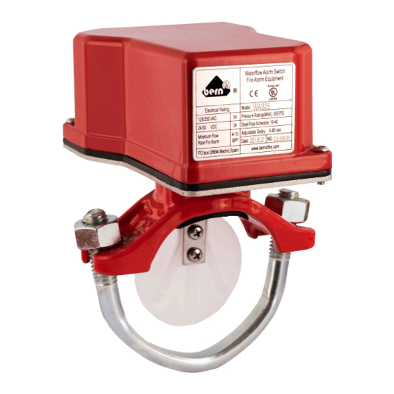
Ground Screw
Delay Adjustment Dial
supply@bernofire.com