Green R/C Model Airplanes Tiger Moth Instruction Manual - Page 4
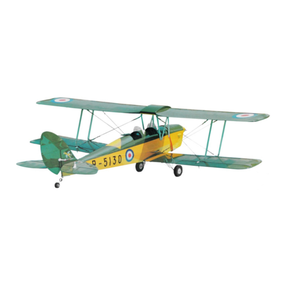
Browse online or download pdf Instruction Manual for Toy Green R/C Model Airplanes Tiger Moth. Green R/C Model Airplanes Tiger Moth 11 pages. The unique almost-ready-to-fly scale 1:7 model of great britain's famous wwii training aircraft
Also for Green R/C Model Airplanes Tiger Moth: Instruction Manual (11 pages)
Step
Step
Step 1. 1. 1. 1. Installation
Step
Installation
Installation in in in in the
Installation
* * * * Open
Bag
Bag
Bag
Bag 1# 1# 1# 1#
Details are shown in
1) Put the fuselage up side down to get access to the opening in the fuselage bottom.
2) Mount the rudder
rudder i i i i ntermediate
rudder
rudder
note that the "Z" end of pushrod is to be inserted in the second small hole in the intermediate
control arm and that the clevis end of the pushrod is to be connected to the rudder servo arm. . . .
3) Install your elevator
elevator
elevator
elevator servo,
4) Connect the clevises of the two sets of elevator
the clevis of the rudder
arm is not yet connected to the throttle
5) Mount the front and the rear windshields
fuselage top to locate the position of windshields). . . .
Step
Step 2. 2. 2. 2. Install
Step
Install
Install
the
the
Step
Install the
the engine
* * * * Open
Bag
Bag 2# 2# 2# 2#
Bag
Bag
1) Before installing the fuel
allow the throttle
throttle control
throttle
throttle
the cable will not interfere with the fuel tank in the fuselage. The location of the hole depends
upon the position of your engine
2) After the fuel tank is installed, put your
3) Referring to the dimensions of your engine; drill holes into the wood
then fix the engine in place with the screws,
connect the throttle
FINAL
FINAL
FINAL
FINAL ASSEMBLY
the fuselage
the
the
fuselage
fuselage
fuselage
to get the fuselage
fuselage
fuselage sub-assembly
fuselage
PARTS
PARTS
the PARTS
PARTS LIST
ntermediate control
ntermediate
ntermediate
servo,
servo, rudder
servo,
rudder
rudder
rudder servo
rudder
rudder
control
control
pushrod
pushrod
rudder control
control pushrod
pushrod to the rudder servo arm. At this stage, the throttle servo
throttle
throttle control
throttle
windshields
windshields
windshields (F02) with the set
Fig.
Fig.
Fig. (1)
Fig.
engine
engine
and
and
engine
engine
engine and
and engine
engine cowl
to get the engine
engine cowl
engine
engine
fuel
tank
tank & & & & fuel
fuel tank
fuel
tank
control
control cable
control
cable
cable
cable (E06) to pass through. This hole must be carefully located so that
engine
engine
engine throttle
throttle
throttle
control
control
cable
cable
throttle control
control cable
cable (E06) to the throttle
ASSEMBLY
ASSEMBLY
ASSEMBLY
sub-assembly
sub-assembly
sub-assembly (F01) and other parts included in the same bag.
LIST
LIST
LIST
control
control arm
control
arm
arm
arm & pushrod
pushrod
pushrod
pushrod with
servo
servo
servo and throttle
throttle
throttle servo
throttle
servo in the servo tray as shown in Fig.(1)
servo
servo
elevator
elevator pull-pull
elevator
pull-pull
pull-pull
pull-pull wires
control
cable
control
control cable
cable
cable (E06) until you have installed your engine.
(1)
(1)
(1) Installation
Installation
Installation
Installation in in in in the
the
the
the fuselage
1. Rudder intermediate control arm
2. Pivot screw
3. Rudder servo and pushrod
4. Rudder pull-pull cable.
5. Throttle servo and control cable
6. Elevator servo and pull-pull wires
cowl
cowl
cowl
cowl
cowl and the hardware needed. . . .
cowl
fuel
tubing
fuel tubing
fuel
tubing (E05), you will need to drill a hole in the firewall to
tubing
throttle
throttle
arm.
arm.
throttle arm.
arm.
your
receiver
your receiver
your
receiver and battery
receiver
screws,
screws,
washers
washers
screws, washers
washers and nuts
throttle
throttle
throttle servo
4
with pivot
with
with
pivot
pivot
pivot screw
screw
screw
screw (C02) in place Please
wires
wires
wires (C05) to the elevator servo arm and
set
set screws
set
screws
screws supplied. (There are holes in the
screws
fuselage
fuselage
fuselage
battery
battery
battery into the fuselage. . . .
wood engine
wood
wood
engine
engine
engine mount
nuts
nuts
nuts supplied. At this stage you can
servo
servo
throttle
throttle
servo and the throttle
throttle arm
Fig.(1)
Fig.(1) .
Fig.(1)
mount
mount beams
mount
beams
beams and
beams
arm
arm of of of of the
arm
the
the
engine.
engine.
the engine.
engine.