GAPOSA XQ40ER Instructions Manual - Page 5
Browse online or download pdf Instructions Manual for Engine GAPOSA XQ40ER. GAPOSA XQ40ER 8 pages. Tubular motors with encoder electronic limits and integrated receiver
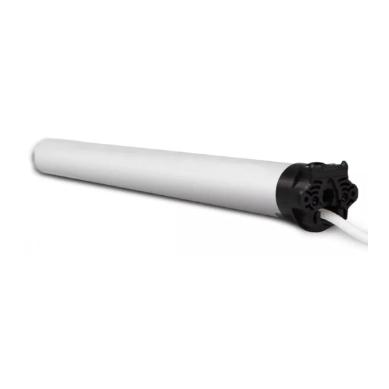
►DESCRIPTION
EN
Tubular motor designed for rolling shutters, blinds and awnings.
It features an integrated receiver (434,15MHz) with remote limit setting
and remote user programmable intermediate stop. It works with GAPOSA
transmitters.
Motor's memory capacity: maximum of 28 transmitters.
Transmitters' range: 20 m indoor and 300 m outdoor.
►INSTALLATION (Fig. 1)
WARNING: Tubular motor must be always installed in the tube first before putting
it into action since the electronic control of the speed variation do not enable the
motor to turn if the limit switch drive do not turn with it.
WARNING: The mounting distance between two motor heads should not be
less than 1/2m;
To complete installation, the motor must be provided with a couple of adaptors
(corresponding with the tube) and a fixing bracket. For a list of the available
accessories, refer to the catalogue.
WARNING: incorrect installation can cause serious injuries. Follow the
installation instructions. Before you remove all unnecessary cables and turn off
any equipment not required for this operation.
- Fix the adaptors to the motor distinguishing the limits ring (Fig. 1.1 A) from the
drive pulley ( (Fig. 1.2 B).
- Turn and lock the clip after inserting it in the drive-shaft groove.
- The fixing bracket (C) must be fixed inside the box or on the awning frame so that
the roller tube (F) is perfectly horizontal and at a height not less than 1,8m.
- Insert the motor (E) into the tube (F) until its end stops against the limits ring.
- Place the motor square pin (D) on the bracket (C) and the cap at the opposite end
of the tube on the fixing plate.
WARNING: Never hit on the head of the motor (D) when you insert it into the
tube.
For the 50 range, with torque up to 15Nm, the minimum tube diameter is
50x1,5mm; for motors with higher torques, the minimum tube diameter is
60x1,5mm. For the 60 range, the minimum tube diameter is 63x1,5mm.
WARNING:
- The screws used to fix the last slat on the tube may be too long and reach the
tubular part of the motor. Use appropriate screws or fixing clips.
- Motor moving parts installed under 2,5m from the ground must be protected.
- A wrong motor installation can damage persons or objects.
►WIRING (Fig. 2)
Check that the mains voltage available on the system is as shown on the label.
The motor mains connection should be executed according to the diagram on the
next page, by qualified technicians able to operate in compliance with the rules.
ATTENTION:
- The power supply must contemplate a switching device with an opening
distance between contacts of at least 3mm.
For models range XQ50 with limit switches without manual override, in case the supply
cable is damaged, it must be replaced by another cable or a special set available by
the manufacturer or his technical assistance (Fig. 3).
►PROGRAMMING THE FIRST TRANSMITTER (Fig. 4)
The first transmitter to be programmed is called MASTER.
It is the only transmitter by means of which You can enter the programming mode.
NOTE: If the MASTER must be replaced, you have to RESET the memory of the
receiver and then program a new transmitter as MASTER.
1. For initial programming provide power only to the motor being programmed;
2. Press and hold Prog-TX button of transmitter till the motor starts moving.
3. Check the motor direction (Ex.: UP as shown aside) then releasethe Prog-TX button
and within 5 seconds press the UP button of the transmitter;
4. If, on the contrary, pressing the Prog-TX button the motor turns DOWNWARDS,
release the Prog-TX button and press the DOWN button of the transmitter within 5
seconds. The MASTER transmitter is now programmed and the direction of the
motor synchronized with the buttons of the transmitter itself.
Now verify the motor directions (if UP on the transmitter corresponds to UP on the
end-product).
ATTENTION! As long as You press the Prog-TX, the motor turns in a direction.
Releasing Prog-TX the motor stops, then pressing it again, the motor turns
again in the opposite direction (sequential fashion).
►PROGRAMMING PROCEDURE IN INSTALLATION MADE UP OF SEVERAL XQ
ER [only for XQ50]
If the installation is made up of several XQ-ER, only one RI motor must be powered
during programming. All the other motors must be disconnected in order to avoid
interferences, unless You program the transmitter through the white button on the
head. The white-button on the motor-head avoids power disconnection of every
motor. This button has the same programming function as the Prog-TX on the
transmitter and for this reason, the programming procedure is the same as described
above. The result, on the contrary, is different since through the white-button you only
program the motor it belongs to.
WARNING! Once the transmitter is recorded, the white button becomes
suitable only to erase the memory of the receiver. In order to add further
transmitters you must use Prog-TX button of the first transmitter (MASTER).
►SETTING THE END LIMITS
1. SETTING THE END LIMITS - UP
1. Press and hold Prog-FC button of the MASTER transmitter till the motor jogs. It is
the motor feedback indicating that the setting procedure begins.
WARNING! Always set the UP LIMIT FIRST! A short stop of the motor's travel
indicates that the motor is running in the setting procedure.
2. Press the UP button of the transmitter: the motor begins to move towards UP limit.
Then follow one of the 2 options. Remember the motor operates in a momentary
fashion:
OPTION 1 - SHUTTER WITH MECHANICAL STOPS OR CASSETTE AWNINGS
- Wait for the motor stops itself because the shutter/awning has reached its upper
reference point;
- The end limit is self-set.
OPTION 2 - SHUTTER OR AWNINGS WITHOUT STOPS
- be prepared to stop the motor at its UP limit;
- for an accurate setting press again Prog-FC button when the shutter/awning is
close to the limit, the motor will run slowly towards the correct UP limit.
- Stop the motor at the desired UP limit pressing the STOP button. The motor jogs;
It is the motor feedback indicating that the UP limit is set.
2. SETTING THE END LIMITS - DOWN
1. Once set the UP limit press the DOWN button of the MASTER transmitter, the
motor begins to move towards DOWN limit.
2. Be prepared to stop the motor at its DOWN limit. For an accurate setting press
again Prog-FC button when the shutter/awning is close to the limit, the motor will
run slowly towards the correct DOWN limit.
3. Stop the motor at the desired DOWN limit pressing the STOP button. The motor
jogs.
It is the motor feedback indicating that the DOWN limit is set and the setting
procedure is made.
►INTERMEDIATE POSITION
One intermediate position can be programmed by the end user and easily deleted
or modified when required. The intermediate position can be reached from any
point between the end limits.
PROGRAMMING INTERMEDIATE POSITION
Move the shutter/awning by using the buttons of the transmitter and stop it at the
desired. Then press simultaneously UP and DOWN buttons till the motor jogs.
The intermediate position is memorized.
USING THE INTERMEDIATE POSITION
Press and hold the button (for more than 5 seconds) till the motor starts to move
towards the intermediate position.
DELETE THE INTERMEDIATE POSITION
Press simultaneously UP and DOWN buttons till the motor jogs.
The intermediate position is deleted.
►ADD A TRANSMITTER/CHANNEL IN THE MEMORY OF THE MOTOR
1. Press and hold PROG-TX button of the MASTER transmitter till the motor starts
moving. The motor is now in the programming mode;
2. Check the motor direction then release the PROG-TX button and press the UP or
DOWN button of the new transmitter within 5 seconds.
In this way you have set the new transmitter in the motor's receiver.
►RESETTING THE MOTOR'S MEMORY
To cancel transmitters from the motor's memory, press PROG-TX and STOP buttons
of the MASTER transmitter simultaneously and release them when the motor jogs
indicating that every transmitter is deleted.
►RESETTING THE MOTOR'S MEMORY WHEN THE MASTER TRANSMITTER
IS LOST
1. Cut the power.
2. Press first PROG-TX and STOP buttons of any GAPOSA transmitter.
3. Switch-on the power and wait for the motor to jog, indicating that any transmitter
is deleted.