GAPOSA M30A Reference Manual - Page 9
Browse online or download pdf Reference Manual for Industrial Equipment GAPOSA M30A. GAPOSA M30A 14 pages. Safety brake
Also for GAPOSA M30A: Reference Manual (11 pages)

IMPORTANT: CHECK THAT THE SAFETY BRAKE HAS NOT UNDERGONE PREVIOUS
TESTS AND STRONG STRESSES.
REINSTATEMENT
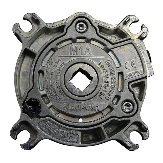
M1A - P200 - M3A - M4A - M7A and M10A safety brakes can stop the rotation of the shaft
to prevent any dangerous acceleration more than once, but each time they must be
reinstated according to the following procedure.
REINSTATEMENT PROCEDURE
(from M1A to M10A models only)
1. Unscrew, according to the sequence in fig. 2, the screws placed on the central body of
the safety brake.
2. Replace the pin projecting out of the central body in its initial position, pushing it in
the opposite direction of the arrow, till the micro switch is set going again; By the M1A
and P200 the hole of the ring must be replaced in the middle of the cavity.
3. Tighten the screws once slightly according to the sequence in fig. 2 and then com-
plete the screwing up always respecting the sequence by a dynamometrical key
setting it according to Tab. A.
ATTENTION: Each time that the M15A, the M20A and the M30A safety brakes stop,
in order to be reinstated, they must be sent back to GAPOSA srl.
MAINTENANCE
If the installation procedure has been respected, the safety brake does not require any
maintenance.
EN
9
