CORNING EDGE8-01U-SP Installation And Testing - Page 11
Browse online or download pdf Installation And Testing for Network Hardware CORNING EDGE8-01U-SP. CORNING EDGE8-01U-SP 13 pages. Tap module
Also for CORNING EDGE8-01U-SP: Installation And Testing (8 pages)
9.5
Table 5 provides a complete guide to the test sequence with the light source at Module "B", or
the "Far end" and the meter at the MTP Tap module "A" ("Near end") tap port testing harness of the
system shown in Figure 15.
Source LC Position at "B"
9.6 To begin testing the tap Portion of the MTP Tap module from Module "B", or the "Far end", to
module "A" TAP port test harness (Figure 15):
Step 1:
Install the Light Source/RJ1 LC connector into LC number 2 port of the EDGE8
module "B" at the "Far End".
Step 2:
Step 2: Install RJ2's LC connector adapter onto LC number 2 of the harness
plugged into the TAP port of the MTP Tap module, "Module A."
LC #2
"A"
RJ2
and
adapter
LC #8
Do NOT
disconnect
0.00 dB
"Near end"
M1
HPA-1005-EDGE8
9.7
Note steps 9.4 and 9.6 CANNOT be combined if using an optical test set with both a source and
a meter in one unit.
STANDARD RECOMMENDED PROCEDURE 003-139-AEN | ISSUE 1 | JANUARy 2017 | PAGE 11 OF 13
B-2
B-4
B-6
B-8
Table 5: Test Sequence
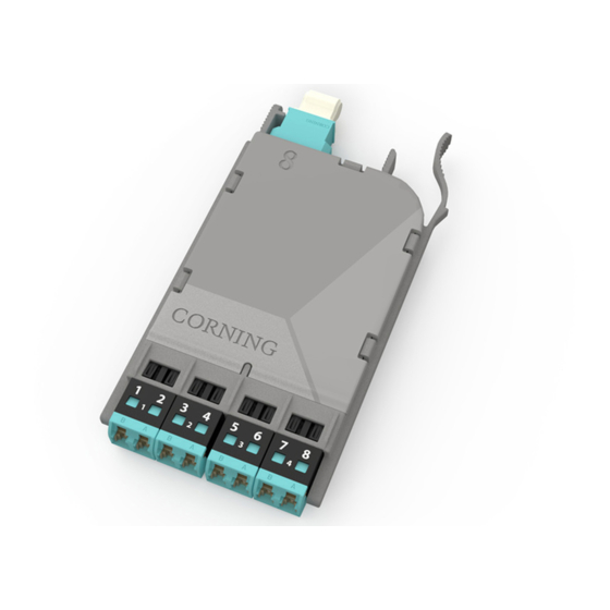
TAP port test harness
EDGE8 MTP Tap Module "A"
Meter # 1 and TAP port test
harness at LC #
2
4
6
8
Note: Fiber loss
depends on length
EDGE8 Module "B"
of system
multimode only
Do NOT
disconnect
RJ1
Light
Source
"Far end"
Figure 15