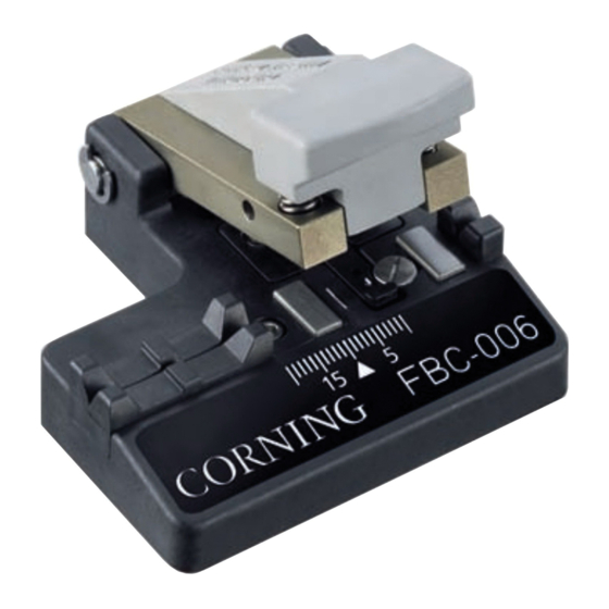
CORNING FBC-006 Operating - Page 2
Browse online or download pdf Operating for Network Hardware CORNING FBC-006. CORNING FBC-006 4 pages. Fiber cleaver

Page 2
4. Cutter Operation
4.1 Make a loop of vinyl tape, adhesive side out, on which
to place cut pieces of fiber. Place the loop in a convenient
location.
4.2 Open the cleaver and make sure that the following
areas of the cleaver are clean:
• Cleaver arm
• Fiber clamps
• Diamond blade • Fiber guide
If any of these areas need cleaning, follow the appropriate
cleaning instructions in Section 5, Maintenance.
4.3 As necessary, insert the proper fiber guide adapter for
your installation according to Section 5, Maintenance.
250 µm and 900 µm Coated Fibers
4.3 Prepare the cable as described in its manufacturer's
documentation.
4.4 Strip at least 4 cm (1.57 in) of coating from the fiber
according to its manufacturer's instructions (Figure 2).
Coated fiber
Figure 2
4.5 Clean the bare fiber by wiping it with a lint-free tissue
soaked in alcohol. From this point on, do not touch the
cleaned fiber with your fingers.
4.6 Place the fiber in the cleaver, aligning the end of the
fiber coating with the scale to give the required cleave
length. Hold the fiber in place with your left thumb or
forefinger (Figure 3).
The bare fiber should extend across the base to the right fiber
guide.
Figure 3
4.7 Gently swing the cleaver arm down so that the upper
fiber clamps are resting on the fiber.
SRP-001-062
• Anvil
4 cm (1.57 in)
bare fiber
Right fiber guide
4.8 Push down on the cleaver with a slow and gentle motion
until you hear a click — the fiber is now cleaved (Figure 4).
Caution: Always use a slow, gentle motion with the
cleaver. Slamming the arm down may damage the diamond
blade, resulting in poor cleaves.
Figure 4
4.9 Remove the cut end of the fiber with tweezers and put
it on the loop of tape (Figure 5).
Figure 5
4.10 After completing use of the cutter, properly dispose of
the tape loop holding the cut fiber ends.
2.9 mm Single-fiber Cable
IMPORTANT: Make sure that the proper fiber guide is
installed in the cleaver (see step 5.2).
4.11 Measure and remove the outer cable jacket and aramid
yarn according to the appropriate connector or splicer
instructions for your installation (Figure 6).
2.9 mm jacket
Figure 6
Bare fiber
900 µm buffer
Issue 7
