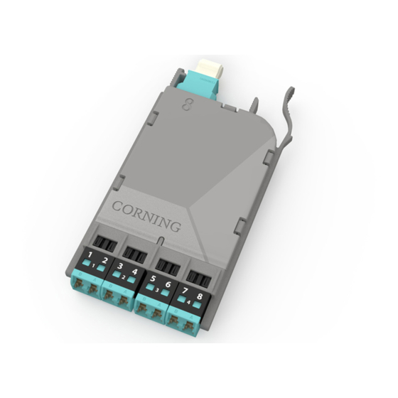
CORNING EDGE8-02U Installation And Testing - Page 13
Browse online or download pdf Installation And Testing for Control Unit CORNING EDGE8-02U. CORNING EDGE8-02U 13 pages. Tap module
Also for CORNING EDGE8-02U: Installation And Testing (8 pages)

10.4. To test the remaining portions of the system (Figure 17):
Step 1:
Install the Light Source/RJ1 LC connector adapter onto LC number 2 of the
harness plugged into the LIVE Port of the MTP Tap module.
Step 2:
Install Meter 1/RJ2's LC connector into the number 1 port of the EDGE8 module,
Module "B".
Step 3:
Install Meter 2/RJ3's LC connector adapter onto LC number 1 of the harness
plugged into the TAP port of the MTP Tap module.
Step 4:
Continue testing through on the even fibers of the harness plugged into the
front-mounted LIVE Port of the MTP Tap module using Tables 2 and 4 for testing
sequences.
LC #2
multimode only
RJ1
and
LC #8
adapter
Do NOT
disconnect
Light
Source
LC #1
RJ3
LC #8
and
adapter
Do NOT
disconnect
0.00 dB
M2
HPA-1007-EDGE8
Corning Optical Communications LLC • PO Box 489 • Hickory, NC 28603-0489 USA
800-743-2675 • FAX: 828-325-5060 • International: +1-828-901-5000 • www.corning.com/opcomm
Corning Optical Communications reserves the right to improve, enhance, and modify the features and specifications of Corning Optical Communications products
without prior notification. A complete listing of the trademarks of Corning Optical Communications is available at www.corning.com/opcomm/trademarks. All other
trademarks are the properties of their respective owners. Corning Optical Communications is ISO 9001 certified. © 2017 Corning Optical Communications. All
rights reserved.
STANDARD RECOMMENDED PROCEDURE 003-139-AEN | ISSUE 1 | JANUARy 2017 | PAGE 13 OF 13
Module harness
EDGE8 MTP Tap Module "A"
TAP port
test harness
"Near end"
Note: Fiber loss
depends on length
EDGE8 Module "B"
of system
RJ2
Do NOT
disconnect
0.00 dB
M1
"Far end"
