CORNING Eclipse Instructions - Page 3
Browse online or download pdf Instructions for Racks & Stands CORNING Eclipse. CORNING Eclipse 5 pages. Wall-mount housing
5.
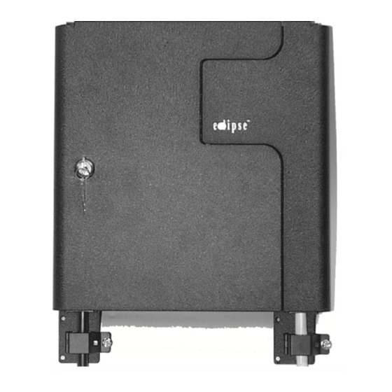
Opening the Wall-Mount unit
both the provider and customer door are secured with
magnets. To open the door, pull on the flange at the top
of the cabinet.
6.
Cable Sheath Removal
Perform cable sheath removal steps as
explained in the instructions for the cable
type you are installing. Suggested sheath
removal lengths are shown.
Buffer Tube to Tray:
Top Entry - 140 cm (55 in)
Bottom Entry - 114 cm (45 in)
Fiber Length Inside Tray Per
Tray Instructions
7.
Cable Strain-relief and Grounding
Step 1:
Pierce grommet at cable entry location.
Step 2:
Feed cable through the grommet.
NOTE: Do not attach the bracket to the unit until you have performed the necessary steps to
strain-relieve the cable.
Step 3:
Scrape paint off the base of the unit where the
cable strain-relief bracket will be installed.
Scrape paint off of the strain-relief bracket
also to ensure a good connection when the
bracket is installed on the unit.
Step 4:
Attach the grounding bar (p/n
GROUND-KIT-1, ordered separately)
to the bracket in the location shown.
Step 5:
Connect to the building ground
by using a ground wire to link the
grounding bar on the unit to the
building ground.
Strain-relieving Cable without Central Member
If the entire length of outside plant cable is routed within
an environmentally controlled building (where temperature
fluctuation is minimal), strain-relieving the cable sheath with
the Universal Cable Clamp (UCC) is adequate.
Step 1:
Install the cable into the clamp per the instruction
provided with the UCC kit.
Step 2:
Attach bracket to the housing using the 6-32
screws provided. Slide grommet into position.
STANDARD RECOMMENDED PROCEDURE 003-499 | ISSUE 4 | SEPTEMbER 2015 | PAGE 3 OF 5
Central Member:
10 cm (4 in)
TPA-3000
Yarn: 20 cm (8 in)
Ground bar
Flange
TPA-3008
TPA-3011
TPA-3013