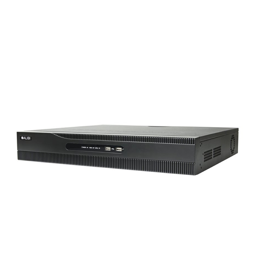
ALIBI ALI-NVR5332P Quick Setup Manual - Page 2
Browse online or download pdf Quick Setup Manual for DVR ALIBI ALI-NVR5332P. ALIBI ALI-NVR5332P 8 pages.

Soft keyboard
One of two on-screen keyboards appears when you click in a field that accepts a entry, such as a password or name or a numerical value.
A third keyboard which includes symbols can also be opened while in the numeric keyboard. The alphanumeric keyboard is shown in
the following picture. Some control keys toggle their function when they are clicked. A numerical keyboard, shown beneath, appears for
numerical entries such as an IP address.
Uppercase /
Lowercase
Switch to
numeric
Soft keyboard - alphanumeric
Switch to
symbols
Switch to
alphanumeric
Switch to
alphanumeric
Switch to
numeric
2
www.Observint.com
Backspace
Enter
Backspace
Enter
Soft keyboard - numeric
Backspace
Enter
Soft keyboard - symbols
Step 1. Connecting alarm devices to the NVR
Wiring alarm inputs to the NVR
You can wire up to 16 alarm inputs to the NVR. Alarm input wiring connects to the RS-485, Alarm IN/OUT connector blocks on the back of the
NVR.
–
Wiring alarm outputs to the NVR
The NVR provides 4 alarm output terminations. These terminations for each output are on the ALARM OUT connector block on the back of the
NVR , and are labeled 1 - G, 2 - G, 3 - G, 4 - G (G = ground termination).
There are 4 jumpers (JP1, JP2, JP3, and JP4) inside the chassis on the alarm termination PC board, associated with ALARM OUT pins 1, 2, 3
and 4 respectively. Initially, these jumpers are in place. If connecting an alarm output to a DC loaded alarm out circuit, the jumper must be in
place. If connecting the alarm output to an AC loaded alarm, the corresponding jumper must be removed. Example: If you connect an AC load
to the alarm output 3 of the NVR, then you must remove the JP 3.
To remove a jumper for AC load alarm circuits:
1.
Disconnect all cabling from the NVR.
2.
Remove the NVR top cover: Remove the two cover screws on the back of the chassis, the slide the cover toward the back until it is free.
3.
Locate the jumper associated with the alarm output you are using for an AC load alarm, then remove it. Save the jumper for use later,
if needed.
4.
Reinstall the NVR top cover.
DC load alarm output circuits
DC loads must operate within the limitation of 12V / 1A. To connect to a DC alarm output, use the following diagram:
+
Sensor
Typical ALARM IN wiring
© 2019 Observint Technologies, Inc. All rights reserved.
