E-T-A 922 Series Installation Manual - Page 7
Browse online or download pdf Installation Manual for Switch E-T-A 922 Series. E-T-A 922 Series 12 pages. Battery isolation/main switches
Also for E-T-A 922 Series: Instructions For Installation Manual (6 pages)

Der Schutzschalter kann auf eine Profilschiene (PS)
im Schaltkasten aufgesteckt (mit Befesti-gungsart
2) oder in einen kundenspezifischen Kasten mit 4
Schrauben eingebaut werden (Fig. 4).
Alternativ dazu kann das Gerät auf einer Montage-
platte mit 4 Schrauben M8 befestigt werden (Fig. 5,
Befestigungsart 5).
AUSBAU
1 Versorgungsspannung abschalten.
2 Elektrischen Anschluss und Steuerleit-ungen lösen.
3 Der Ausbau erfolgt in umgekehrter Reihenfolge.
Elektrischer Anschluss
ACHTUNG!
EINPOLIG:
• Bei Betriebsspannungen > 48 V auf die Polarität
achten (gekennzeichnet durch Aufkleber auf der
Haupt-Anschlussseite).
ZWEIPOLIG:
• Der rote Kipphebel entspricht dem (+) Pol.
1 Stromversorgung abschalten.
2 Stromversorgungskabel von der Batterie auf „I"
anschließen (Fig. 6).
3 Steuerleitung und Hilfskontakte gemäß Fig. 7
(921/922) oder Fig. 8 (437) anschließen.
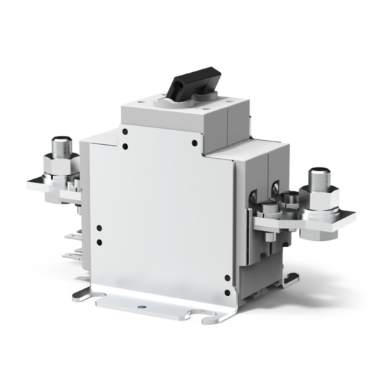
For non-automative applications, the switch unit may
be fitted to rail (PS) provided in a control cabinet (with
mounting method 2) or mounted in a custom designed
enclosure by means of 4 bolts M4 (fig. 4), alternatively
the switch unit is provided with brackets for base
mounting by means of 4 bolts M8 (fig. 5, mounting
method 5).
REMOVAL
1 Disconnect power supply.
2 Disconnect the terminals and the control cable.
3 Reverse the installation procedure.
Electrical connection
CAUTION!
SINGLE POLE:
• Observe the correct polarity (identified by label on
the main connection side) when operating voltages
above 48 V are applied!
DOUBLE POLE:
• The red toggle identifies the positive pole (+).
1 Disconnect power supply.
2 Connect the main battery cable to terminal I of the
switch unit.
3 Connect the remote control circuitry and auxiliary
contacts as shown in fig.7 (921/922) or fig. 8 (437).
7
