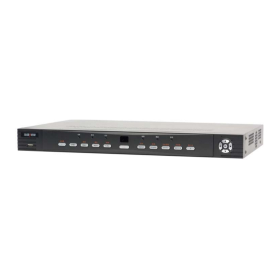
HIKVISION DS7208HVI-ST/SE Product/Maintenance Manual - Page 17
Browse online or download pdf Product/Maintenance Manual for DVR HIKVISION DS7208HVI-ST/SE. HIKVISION DS7208HVI-ST/SE 20 pages.

②. No VOUT Output
Step 1: measurement HK-5 (TVS9) whether short circuit, or replacement
Step 2: measuring 75Ωresistance (RS117) impedence, or replacement
Step 3: monitor's signal lines connected to the probe, directly from SGM9111
(US7) chip PIN 4 draw out the VOUT signal, or replacement
Step 4: measuring 75Ω resistance (RS188), or replacement, and then monitor's
signal lines connected to the probe, directly lead CVBS -VOUT signal
from 75Ω resistance (RS188) end, or KY2010 ruled out
③. Image Problem
Phenomenon 1: there is no video signal, first exclude HK-5 (TVS1-8) whether
short circuit, or replacement; Measuring 75Ω(RV1-8) resistance, or
replacement, and then ruled out 100Ωresistance (RU1-8); Finally ruled out
TW2866 (can directly introduce video signal into TW2866 chip video input
end,PIN13/17/21/25, to rule out the chip is normal or not)
Phenomenon 2: a few channel image black screen, first rule out the software
settings, otherwise introduce video signal into TW2866 chip video input end,PIN
13/ 17/21/25, to rule out the chip is normal, or replacement
Phenomenon 3: all black and white images or flower screen, to rule out 27 M
(Y4), then rule out software, or change TW2866
CG1, CG2
