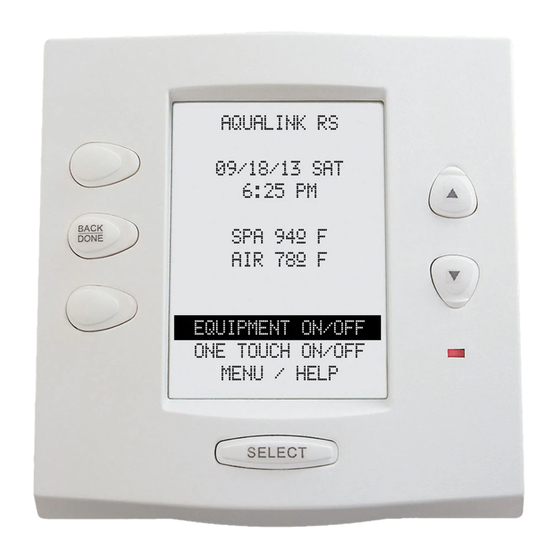
Jandy AquaLink RS6 Installation Manual - Page 13
Browse online or download pdf Installation Manual for Control Panel Jandy AquaLink RS6. Jandy AquaLink RS6 16 pages. Dual equipment systems

- 1. Section 2. System Overview
- 2. Plumbing Diagrams
- 3. Connecting Power and Mounting Bezel
- 4. Connecting Control Panel Cable to Pcb
- 5. Section 3. Power Center Connection (Low Voltage)
- 6. Dip Switch Functions
- 7. Dip Switch Settings for Pool and Spa Combination
- 8. Section 5. Dual Equipment Wiring Diagram
4.3
DIP Switch Settings for Pool or Spa Only
S1 DIP Switch #
1
AUX1= any equipment
2
AUX2= any equipment
3
AUX3= any equipment
4
Heater cool down operates.
5
Normal operation
6
Spare
7
Spare
8
After thermostat setting has been reached,
heater will remain OFF for 3 minutes.
S2 DIP Switch #
1
The AquaLink RS will be able to control a
Solar Heating system (If a solar sensor is
connected to the solar sensor input).
2
3
4
4.4
DIP Switch Settings for heat Pump Installation
This table shows how to configure the system for SOLAR PRIORITY or HEAT PUMP PRIORITY.
GREEN 10-PIN
DIP S2-1
TERMINAL BAR
OFF
No sensor installed
OFF
Sensor installed
OFF
Sensor installed
ON
No sensor installed
ON
Sensor installed
ON
Sensor installed
OFF
OFF
RS485 hEAT PUMP
Not connected
Not connected
Connected
Not connected
Not connected
Connected
AUX1= Pool Cleaner
AUX2= Low Speed for a two-speed filter pump.
Filter pump circuit becomes High Speed.
No change
Heater cool down disabled.
Factory adjustment- when this switch is on,
temperature delays are eliminated and solar
temperature is displayed.
Do not leave this switch in the ON position.
No change
No change
Heat Pump installed; after thermostat setting
has been reached, heater will remain OFF for 5
minutes.
The AquaLink RS will be able to control a Heat
Pump. (The AquaLink RS will not be able to
control a Solar Heating system.)
NOT USED
NOT USED
NOT USED
DESCRIPTION
In this configuration there is no Solar Heating and no
Heat Pump. Extra AUX is available.
In this configuration there is Solar Heating and there
is Solar Priority. There is no Heat Pump.
In this configuration there is Solar Heating and there
is Solar Priority. There is Heat Pump. There is Heat
Pump Priority.
In this configuration there is no Solar Heating. There
is a mechanically connected Heat Pump. There is
Heat Pump Priority (a limited implementation).
In this configuration there is no Solar Heating. There
is a mechanically connected Heat Pump. There is
Heat Pump Priority (full implementation).
In this configuration there is no Solar Heating. There
is an RS485 controlled Heat Pump. There is Heat
Pump Priority.
Page 13
ON
ON
