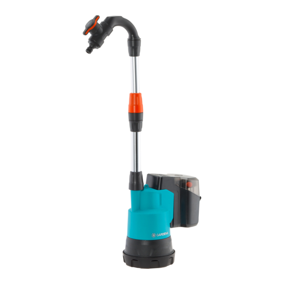
Gardena CW Pump 2000/2 Li-18 Operator's Manual - Page 7
Browse online or download pdf Operator's Manual for Water Pump Gardena CW Pump 2000/2 Li-18. Gardena CW Pump 2000/2 Li-18 16 pages.

Mode button:
The pump has 3 power levels, which can be called up one
after the other with the mode button.
ß
v Push the Mode button
m
ß
ß
ß
The LEDs
and
and
L
1
L
2
L
m
m
m
power level.
Power levels:
Mode 1:
Pumping capacity: max. 1100 l/h – max. 0.4 bar
Battery life: approx. 60 minutes
Ideal for dewatering with short hoses, suction of foils, filling
watering cans or irrigation of sensitive plants.
Mode 2:
Pumping capacity: max. 1700 l/h – max. 1.3 bar
Battery life: approx. 30 minutes
Ideal for dewatering with longer hoses, irrigation with
watering spray.
Mode 3:
Pumping capacity: max. 2000 l/h – max. 2.0 bar
Battery life: approx. 15 minutes
Ideal for drainage with height differences or long hoses,
irrigation with shower or sprinkler, cleaning or feeding
a garden shower.
Applications:
CAUTION! Destruction of the battery!
The battery unit is destroyed when it is immersed in
water.
v Do not immerse the battery unit in the water.
Observe the minimum water level (see 7. TECHNICAL
DATA).
Use in flat containers [ Fig. O5 ]:
Art. 1748: The pump is equipped with a hose connector
which allows high flow rates.
Art. 1749: If the rain water tank pump is placed in flat con-
tainers, e. g. to empty a paddling pool, the telescopic pipe
can be removed and replaced with the 33.3-mm (G1)
GARDENA Tap Connector Art. 18202.
(D)
1. Place the battery unit
water.
4. MAINTENANCE
DANGER! Risk of injury!
Injury when the product starts accidentally.
v Remove the battery before you maintain the
product.
To clean the pump:
DANGER! Risk of injury!
Risk of injury and risk of damage to the
product.
on the control panel.
illuminate according to the
3
in a place protected from
2. Place the pump in the container.
3. Start the pump.
Flat suction [ Fig. O6 ]:
In normal operation (with foot
of approx. 25 mm is achieved. With flat suction (without
(9)
foot
) a residual water level of approx. 5 mm is achieved.
(9)
1. Turn the foot
anti-clockwise and remove the foot
(bayonet lock).
2. Make sure that the filter
3. For reassembling the suction foot, see 4. MAINTENANCE.
The pump must not be operated without the filter
To pump water from container [ Fig. O7 ]:
For Art. 1749: The length of the telescopic pipe
be adjusted in such a manner that the pump does not
touch the bottom of the container; this way, dirt in the
container is kept away from the pump.
1. Open the bracket on the battery container
(D)
2. Hang the battery unit
the container or place it in a suitable, flood-proof place.
3. For Art. 1748: Hang the pump into the container using
a rope (do not hang it with the cable).
For Art. 1749: Hang the pump with the telescopic
(3)
tube
into the container.
4. Start the pump.
To start the pump [ Fig. O8 ]:
To start:
(8)
1. Open the cover
.
(B)
2. Put the battery
into the battery holder
audibly engages.
(8)
3. Close the cover
until it engages noticeably.
4. Push the On / Off button
The Pump starts. Depending on the length of the hose
and the type of installation, it may take some time for
the pump to deliver the water.
To stop:
1. Push the On/Off button
The Pump stops.
2. Push both locking buttons
(D)
from the battery holder
v Do not clean the product with a water jet
(in particular high-pressure water jet).
v Do not clean with chemicals including petrol or
solvents. Some can destroy critical plastic parts.
v Clean the pump with a damp cloth.
To clean the filter [ Fig. M1 / M2 / M3 ]:
In order to ensure continuous trouble-free operation, the
(10)
filter
should be cleaned at regular intervals.
After pumping dirty water, the filter must be cleaned imme-
diately.
(9)
), a residual water level
(10)
is inserted correctly.
(10)
.
(3)
should
(D)
.
on the outside, on the side of
(D)
until it
(s)
(P)
on the control panel
.
(s)
(P)
on the control panel
.
(A)
and remove the battery
.
(9)
(B)
15
