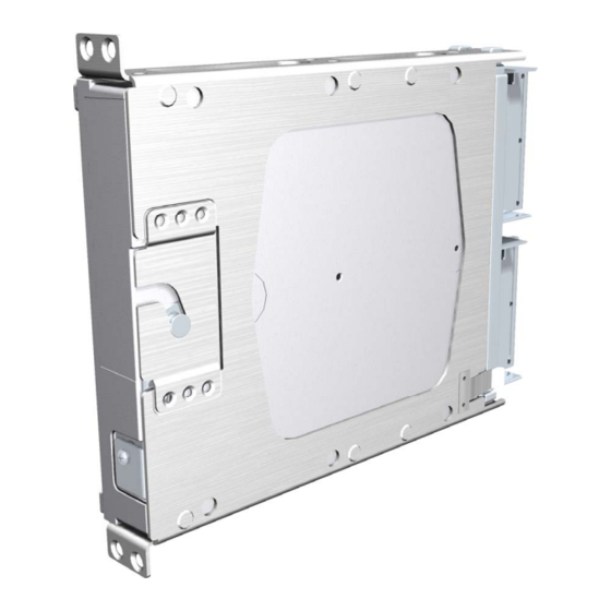
Garmin GEA 71 Installation Manual - Page 16
Browse online or download pdf Installation Manual for Avionics Display Garmin GEA 71. Garmin GEA 71 34 pages.

2.3
Interface Considerations
The GEA 71 interfaces with the GIA 63(W) IAU and with various sensors on the aircraft. Fabrication of
a wiring harness is required.
2.3.1
Airframe/Engine Sensor Considerations
There are several sensors that are normally found on single- and twin-engine aircraft. The GEA 71 is
designed to interface with such sensors, giving the unit complete configurability for different applications.
Table 2-1 shows typical engine/airframe sensors that can be connected with the GEA 71. Note that this
table is not an all-inclusive list of sensors that can be used.
Exhaust Gas Temperature (EGT)
Oil Pressure
Fuel Flow
Manifold Air Pressure (MAP)
Alternator/Volts Meter
Door Open/Closed Annunciation
Low/High Compressor RPM (N1, N2)
2.3.2
Engine/Airframe Sensor Installation
Engine/airframe sensors to be used must be approved by the aircraft manufacturer and Garmin. Follow
the sensor manufacturer recommended installation procedures. Wires routed too close to spark plugs,
plug wires, or magnetos may result in erratic readings. Ensure that EGT, CHT, and other sensor wires do
not come in contact with exhaust manifolds or any other extreme heat sources. Give proper attention to
each sensor's requirements for polarity, voltage, wire type, and mounting.
2.4
Cabling and Wiring
Use AWG #24 or larger wire for all connections unless otherwise specified by the aircraft manufacturer
or Garmin. The standard pin contacts supplied in the connector kit are compatible with up to AWG #22
wire. In cases where some installations have more than one unit sharing a common circuit breaker, sizing
and wire gauge is based on aircraft circuit breaker layout, length of wiring, current draw of units, and
internal unit protection characteristics. Do not attempt to combine more than one unit on the same circuit
breaker unless it is specified on aircraft manufacturer approved drawings.
In some cases, a larger gauge wire such as AWG #16, #18, or #20 may be needed for power connections.
Special thin-wall heat shrink tubing is also provided to insulate the extended barrels inside the backshell.
If using #16 or #18 barrel contacts, ensure that no two contacts are mounted directly adjacent to each
other. This minimizes the risk of contacts touching and shorting to adjacent pins and to ground.
Ensure that routing of the wiring does not come in contact with sources of heat, RF or EMI interference.
Check that there is ample space for the cabling and mating connectors. Avoid sharp bends in cabling and
routing near aircraft control cables.
2.5
Cooling Air
Refer to the G1000 System Installation Manual, Garmin part number 190-00303-00, for information on
cooling requirements.
Page 2-2
Revision F
Table 2-1. Typical Engine/Airframe Sensors
Cylinder Head Temperature (CHT)
Oil Temperature
Fuel Level (L/R)
Engine RPM
Amps
Pitot Heat Annunciation
Generator Power
GEA 71 Installation Manual
190-00303-40
