Garmin GNC 250 Maintenance And Repair Manual - Page 7
Browse online or download pdf Maintenance And Repair Manual for Avionics Display Garmin GNC 250. Garmin GNC 250 20 pages. Garmin gnc 250: quick reference
Also for Garmin GNC 250: Pilot’s Quick Reference Manual (25 pages), Installation Manual (44 pages)

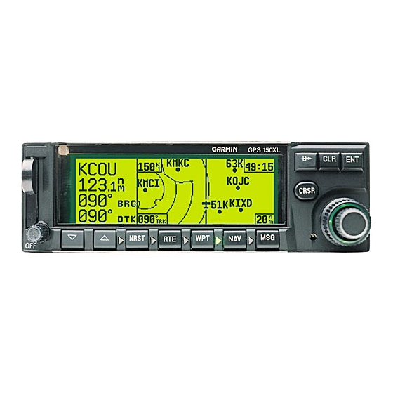
1.2.1 Control/Display Unit (CDU)
The Control/Display Unit is an assembly consisting of eleven keycaps, keypad board, optical lens,
vacuum fluorescent display (VFD) and board with drivers, photocell and screws, housed in a die cast
bezel with a dual concentric rotary switch and two knobs. The VFD is a 4 row by 20 column unit
with variable intensity. This display provides excellent day and night visibility from wide viewing
angles. The front panel provides function selection and alphanumeric input to the CPU board
Assembly via 11 push-buttons and the dual concentric rotary switch. There are two LEDs behind
each keycap, providing backlighting for night time use.
The block diagram in Figure 2 shows the interaction between components on the Control/Display
Unit.
Figure 2. Control/Display Unit Block Diagram
4
