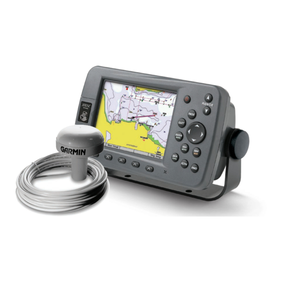
Garmin GPSMAP 3005C Installation Instructions Manual - Page 8
Browse online or download pdf Installation Instructions Manual for Marine GPS System Garmin GPSMAP 3005C. Garmin GPSMAP 3005C 10 pages. Declaration of conformity
Also for Garmin GPSMAP 3005C: Quick Reference Manual (2 pages), Template Manual (1 pages), Quick Reference (2 pages), Installation Instructions Manual (17 pages), Declaration Of Conformity (1 pages)

Wiring to an Optional Alarm
The GPSMAP 3000 series chartplotter can be used with a lamp, a horn, or both, to sound or flash an alert when the chartplotter displays a
message. The alarm does not need to be wired for the GPSMAP 3000 chartplotter to function. The alarm circuit switches to a low-voltage state
when the alarm sounds. The maximum current is 100 mA, and a relay (not included) is needed to limit the current from the chartplotter to 100
mA. To select between visual and audible alerts, install a switch.
GPSMAP 3000 Series
Chartplotter
Marine Video Cable
The GPSMAP 3006/3206/3010/3210 chartplotters have video input and output capabilities, and a video cable is provided with those units. The
GPSMAP 3005/3205 chartplotters do not have video input or output capabilities, so no cable is provided with those units.
The Marine Video 17-pin cable allows input of NTSC (National Television System Committee)/PAL (Phase Alternate Line) composite video
sources, and PC monitor output. Marine Video inputs are only available on the chartplotter to which they are attached and will not transmit over
the Garmin Marine Network.
➊
and
➋
VIDEO 1 and VIDEO 2 Inputs (RCA connectors) allow input from two separate NTSC/PAL compatible video devices, such as VCR,
DVD, TV, or a video camera. The chartplotter can display one video input at a time or alternate between the two. See the owner's manual for
details. Sound from a video source must be attached to a separate stereo/audio system. The video output from video device attaches to the
Video 1 (Black Cable) or Video 2 (Gray Cable) RCA connectors.
➌
Use the PC monitor output (HD 15-pin) connector for remote viewing of the chartplotter display on a computer monitor. The remote monitor
must be capable of at least VGA resolution and have multi-sync capability.
➌
➌
➋
➋
➊
➊
Garmin
Wiring to a lamp, a horn, or both.
PIN 2
PIN 2
PIN 17
PIN 17
Marine Video Cable
Marine Video Cable
End View
End View
Wire
Color
FUSE
3 A
Red (power)
Black (gnd)
Yellow
(alarm)
Note
Connector
RCA-1 Center
➊
RCA-1 Outer
RCA-2 Center
➋
RCA-2 Outer
HD-15 Pin 1
➌
HD-15 Pin 2
PIN 1
PIN 1
HD-15 Pin 3
HD-15 Pin 5
PIN 7
PIN 7
HD-15 Pin 6
HD-15 Pin 7
HD-15 Pin 8
HD-15 Pin 10
HD-15 Pin 13
HD-15 Pin 14
HD-15 Pin shell
+
-
Battery
10–33 Vdc
Horn
RElAY
100 mA MAX
COIl CURRENT
Pin
Function
2
Video 1 in (black jacket)
6
Video 1 in, gnd
11
Video 2 in (gray jacket)
15
Video 2 in, gnd
1
VGA, analog-red
4
VGA, analog-green
3
VGA, analog-blue
13
VGA, analog, gnd
8
VGA, analog-red, gnd
8
VGA, analog-green, gnd
8
VGA, analog-blue, gnd
13
VGA, sync-Gnd
7
VGA, H-sync
12
VGA, V-sync
9
VGA, overall shield
GPSMAP 3000 Series Installation Instructions
lamp
