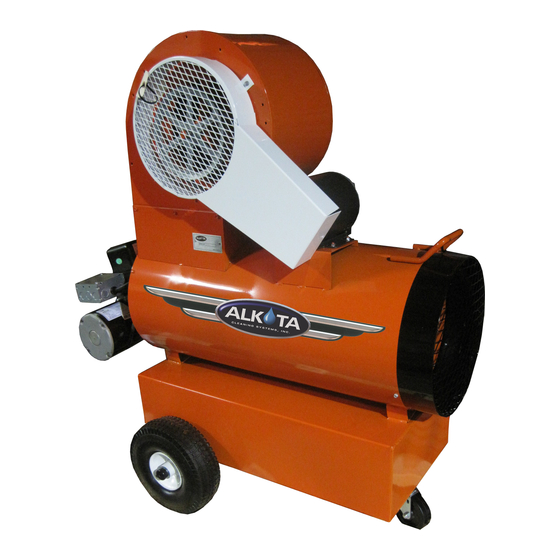
ALKOTA 210 Specifications - Page 7
Browse online or download pdf Specifications for Heater ALKOTA 210. ALKOTA 210 19 pages.

AIR BAND ADJUSTMENT
NOTE: The air band adjustment on this burner
has been preset at the factory (elevation
approximately 1400 feet). On equipment installed
where elevation is substantially different, the air
band(s) must be readjusted.
1. Loosen the cap screw retaining the air bands.
2. Move the air bands as indicated below with
the
machine
NOTE:
The air band should be set so the
exhaust gives the smoke spot specified in the
GENERAL
section
SPECIFICATIONS on a Shell-Bacharach scale.
If a smoke tester is not
available,
a
exhaust, oily odor, or
sweet smell
indicates
insufficient air while eye-
burning fumes indicate
too much air.
3.
Tighten the cap screw
retaining the air bands.
FUEL PUMP FILTER
SUNDSTRAND PUMP
1.
Shut off fuel supply.
2.
Loosen the 4 screws holding the cover to the
fuel pump housing.
3.
Take cover and cover gasket off and pull
strainer off of pump housing.
4.
Clean out any dirt remaining in the bottom of
strainer cover. If there is evidence of rust
inside of the unit, be sure to remove water in
supply tank and fuel filter.
5.
Turn on fuel supply. Failure to do so will result
in fuel pump damage.
PART NUMBER
V00-14283-5
ECN-02981 Supersedes 06-05-01 Z08-00062
OIL BURNER MAINTENANCE
OIL FIRED CLEANERS
in
operation.
of
the
MACHINE
smoky
PART NUMBER
V00-14283-2
DANFOSS PUMP
1.
Shut off fuel supply.
2.
Loosen the 2 screws with 7/64 allen wrench
one turn.
3.
Turn cover counter clockwise and pull strainer
and cover off of pump housing.
4.
Clean out any dirt remaining in the bottom of
strainer cover. If there is evidence of rust
inside of the unit, be sure to remove water in
supply tank and fuel filter.
5.
Reinstall reverse of removal.
6.
Turn on fuel supp
TRANSFORMER TEST
1. Remove burner junction box cover.
2. Turn on burner and make sure ignition
transformer is receiving rated voltage.
3. Turn off burner.
4. Loosen screw and swing transformer away from
burner gun assembly.
5. Turn on burner.
6. Short
the
high
CAUTION:
Use screwdriver
insulated handle to avoid shock.
7. Open gap by drawing screwdriver away from
one electrode while touching the other.
8. The spark should jump between 5/8 inches
and 3/4 inches, if it doesn't jump, replace
the transformer.
9. Turn burner off.
10.Partially close transformer. Check if buss bars
align and contact transformer electrodes. If
buss bars do not contact, see Buss Bar
Alignment.
11.Close transformer, r
.
tighten screw
ly.
PART NUMBER
V00-99004
voltage
terminals.
with
a
eposition retainer clip and
08-05-03 Z08-00062
well
