Garmin GTX 320A Installation Manual - Page 22
Browse online or download pdf Installation Manual for Marine Radio Garmin GTX 320A. Garmin GTX 320A 43 pages. Garmin gtx 320/320a transponder installation manual
Also for Garmin GTX 320A: Pilot's Manual (4 pages), Pilot's Manual (8 pages), Installation Manual (37 pages)

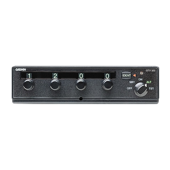
3.2.1 Function Selection Switches
The function selector switch is a five position rotary switch. The five positions are:
OFF
Turns off all power to the GTX 320/320A.
SBY
Turns the transponder on, but when in SBY the transponder will not reply to any
interrogations from the ground radar system.
ON
Places the transponder in Mode A, the identification mode. In addition to the aircraft's
identification code, the transponder will also reply to altitude interrogations (mode C) with signals
that do not contain altitude information.
ALT
Places the transponder in Mode A and Mode C, the identification and altitude reporting
modes to respond to ATC aircraft identification interrogations and altitude interrogations with
standard pressure altitude (29.92 inches Hg.) received from an external altitude digital encoder. The
ALT position may be used in aircraft that are not equipped with the optional altitude encoder,
however, the only response will be discreet signals that do not contain altitude information.
Any time the function switch is in the ON or ALT position the transponder becomes an active part of the
beacon system. Select ON or ALT as late as practical prior to takeoff and to OFF or SBY as soon as
practical after completing landing roll unless the change to SBY has been accomplished previously at the
request of ATC.
TST
Turning the switch to the TST position tests the reply indicator. The TST position is spring
loaded and must be held momentarily. When released, it will automatically return to the ALT
position.
3.2.2 Code Selection
The code selector consists of four, eight position switches that provide 4,096 active identification codes.
When making routine code changes, you should avoid inadvertent selection of codes 7500, 7600, or 7700 thereby
causing momentary false alarms at automated ground facilities. For example when switching from code 2700 to
code 7200, switch first to 2200 then 7200, NOT to 7700 and then 7200.
This procedure applies to nondiscrete code 7500 and all discrete codes in the 7600 and 7700 series (i.e., 7600-
7677, 7700-7777) which trigger special indicators in automated facilities. Only nondiscrete code 7500 will be
decoded as the hijack code. An aircraft's transponder code (when available) is utilized to enhance the tracking
capabilities of the ATC facility, therefore you should not turn the transponder to SBY when making routine code
changes.
See the Aeronautical Information Manual (AIM) for a detailed explanation of the identification codes.
Page 3-2
Rev M
NOTE
NOTE
GTX 320/320A Installation Manual
190-00133-01
