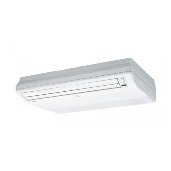
Fujitsu ABYF24LAT Operating Manual - Page 3
Browse online or download pdf Operating Manual for Air Conditioner Fujitsu ABYF24LAT. Fujitsu ABYF24LAT 17 pages. Floor console / under ceiling dual type
Also for Fujitsu ABYF24LAT: Service Manual (36 pages)

FEATURES AND FUNCTIONS
AUTOMATIC OPERATION
G COOLING MODEL
Merely press the START/STOP button, and the unit will
begin automatic operation in the Cooling or Dry mode as
appropriate, in accordance with the thermostat setting
and the actual temperature of the room.
G HEAT & COOL MODEL (REVERSE CYCLE)
Merely press the START/STOP button, and the unit will
begin automatic operation in either the Heating, Cooling
or Monitor modes as appropriate, in accordance with the
thermostat setting and the actual temperature of the room.
SLEEP TIMER
G COOLING MODEL
When the SLEEP timer button is pressed during Cooling
or Dry mode, the thermostat setting is gradually raised
during the period of operation. When the set time is
reached, the unit automatically turns off.
G HEAT & COOL MODEL (REVERSE CYCLE)
When the SLEEP timer button is pressed during Heating
mode, the air conditioner's thermostat setting is gradu-
ally lowered during the period of operation; during Cool-
ing or Dry mode, the thermostat setting is gradually raised
during the period of operation. When the set time is
reached, the unit automatically turns off.
NAME OF PARTS
9374379262-03_OM_en.p65
4
5
6
2
3
2
WIRELESS REMOTE CONTROLLER
The WIRELESS REMOTE CONTROLLER allows convenient
control of air conditioner operation.
OMNI-DIRECTIONAL AIR FLOW
(SWING OPERATION)
Three-dimensional control over air direction swing is possi-
ble through dual use of both an UP/DOWN air direction swing
and RIGHT/LEFT air direction swing. Since UP/DOWN air
direction flaps operate automatically according to the ope-
rating mode of the unit, it is possible to set air direction based
on the operating mode.
MILDEW-RESISTANT FILTER
The AIR FILTER has been treated to resist mildew growth,
thus allowing cleaner use and easier care.
Indoor Unit
1 Operating Control Panel
2 MANUAL AUTO button
3 Remote Controller Signal Receiver
4 OPERATION Indicator Lamp (green)
5 TIMER Indicator Lamp (orange)
6 FILTER Lamp (red)
G
If the TIMER indicator lamp flashes when
the timer is operating, it indicates that a
fault has occurred with the timer setting
(see page 15 AUTO Restart).
7 Intake Grille
8 Air Filter
9 UP/DOWN Air Direction Flaps
0 RIGHT/LEFT Air Direction Louvers
(behind UP/DOWN Air Direction Flaps)
A Drain Hose
2/4/10, 3:06 PM
En-2
