A-M Systems 4000 Instruction Manual - Page 6
Browse online or download pdf Instruction Manual for Amplifier A-M Systems 4000. A-M Systems 4000 12 pages. Multirecord extracellular amplifier

2. Front and Rear Panels
This chapter describes the front and rear panel controls and connectors on the Model 4000.
When you receive your Model 4000, confirm that everything in the packing list is included. Make
sure there are no obvious signs of internal damage, such as rattling. Pick up the amplifier and tilt in
gently from side to side, and listen for anything that might be loose. If you hear any suspicious
noises, contact A-M Systems immediately.
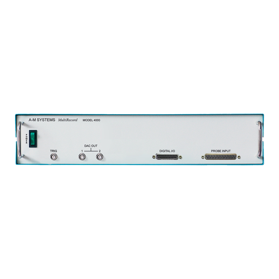
Front Panel
Power
The Model 4000 has an illuminated power supply switch that will light
when line power is passing through it. If it does not light then there is no
line power to the amplifier.
Probe Input
This DB37 connector is the connection point for the TBSI headstage. It is
directly compatible with either a M-Series 30-Channel Headstage or a T-
Series 32-Channel Headstage output cable.
Datawave Sciworks Passthrough Connectors
These connectors provide easy access to a variety of functions generated
by Datawave Sciworks. For additional information on their functionality,
please refer to the Datawave Sciworks Instruction Manual.
Figure 1.
Power switch
Figure 2.
Probe Input
PROBE INPUT
Figure 3.
Sciworks
Passthrough Connectors
DAC OUT
TRIG
1
2
DIGITAL I/O
6
