A-M Systems 2100 Instruction Manual - Page 6
Browse online or download pdf Instruction Manual for Measuring Instruments A-M Systems 2100. A-M Systems 2100 19 pages. Isolated pulse stimulator

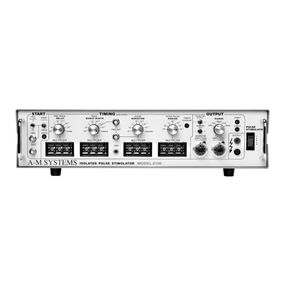
Timing
Four sets of controls govern the timing of
pulse generation. Each set contains two
values which are multiplied together to
determine the actual timing value. The rotary
knob (rate selector) provides the approximate
timing value and the lever wheel switch bank
(
) provides a time resolution of
MULTIPLIER
three decimal digits. The following diagram
shows most of the important relationships.
These controls determine the time duration between the initiating trigger
DELAY:
event and the beginning of the pulse burst. If this rate selector is set to
multiplier is set to
These controls determine the time period in which one or more pulses
BURST WIDTH:
may be delivered. Once started a pulse may outlast the burst width. If this rate
selector is set to
pulse will occur. If the
the
rate until the burst time ends. Pulses are never truncated by a short
PERIOD
.
WIDTH
These controls determine the
DURATION:
length of each pulse. If this rate selector is set
to
, the duration is set to half of the
SQUARE
period, regardless of the
These controls set the period of time
PERIOD:
between adjacent pulse events within the
burst. It also forces a minimum "dead time"
between recognized input triggers following
a burst of one or more pulses. This can be used to prevent over stimulation of a tissue
without requiring excessive delay between the triggering event and the stimulating
pulse.
A-M Systems
there is no delay.
0.00
, or to any time shorter than the pulse duration, only a single
SINGLE
is longer than the period, pulses will be emitted at
BURST WIDTH
setting.
MULTIPLIER
131 Business Park Loop, P.O. Box 850 Carlsborg, WA 98324
Telephone: 800-426-1306 * 360-683-8300 * FAX: 360-683-3525
E-mail: [email protected] * Website:
http://www.a-msystems.com
or the
NONE
BURST
3
