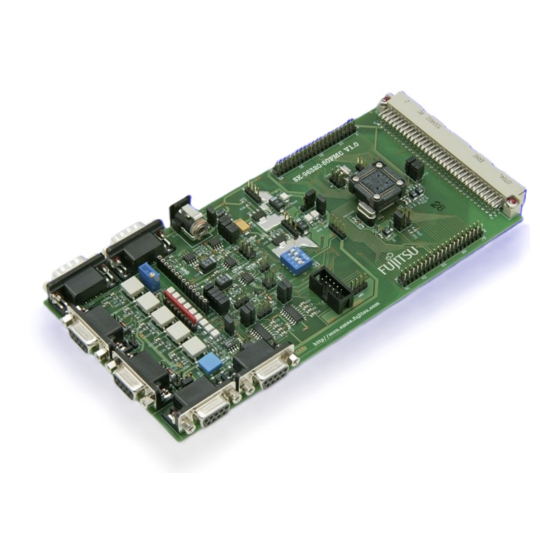
Fujitsu SK-96320-80PMC User Manual - Page 16
Browse online or download pdf User Manual for Motherboard Fujitsu SK-96320-80PMC. Fujitsu SK-96320-80PMC 34 pages.
Also for Fujitsu SK-96320-80PMC: User Manual (34 pages), User Manual (34 pages)

3.5 UART"A" (JP: 1, 2, 31)
One RS232-transceiver (U1, X3) can be connected to one of the microcontroller's UART
interfaces.
JP1, JP2 connect UART 2 to the RS232-transceiver (U1, X3)
JP31
JP2 (UART"A"RxD)
JP1 (UART"A"TxD)
JP31 (RTS-CTS)
By default, UART2 is connected to UART"A".
3.6 UART"B" (JP: 6, 8, 32)
One RS232-transceiver (U3, X5) can be connected to one of the microcontroller's UART
interfaces.
JP6, JP8 connect UART 3 to the RS232-transceiver (U3, X5)
JP32
JP6 (UART"B"RxD)
JP8 (UART"B"TxD)
JP32 (RTS-CTS)
By default, UART3 is connected to UART"B".
UART "B" can be used for serial asynchronous Flash programming.
FMEMCU-UG-960010-12
Downloaded from
Elcodis.com
electronic components distributor
Chapter 3 Jumpers and Switches
Some programs (e.g. Terminals) need a connection between CTS and RTS
Jumper
Setting
Closed
Open
Closed
Open
Closed
Open
Some programs (e.g. Terminals) need a connection between CTS and RTS
Jumper
Setting
Closed
Open
Closed
Open
Closed
Open
SK-96320-80PMC User Guide
Description
SIN2 of the MCU is connected to UART"A"
SIN2 of the MCU is not connected to UART"A"
SOT2 of the MCU is connected to UART"A"
SOT2 of the MCU is not connected to UART"A"
RTS and CTS of X3 are connected
RTS and CTS of X3 are not connected
Description
SIN3 of the MCU is connected to UART"B"
SIN3 of the MCU is not connected to UART"B"
SOT3 of the MCU is connected to UART"B"
SOT3 of the MCU is not connected to UART"B"
RTS and CTS of X5 are connected
RTS and CTS of X5 are not connected
- 16 -
© Fujitsu Microelectronics Europe GmbH
