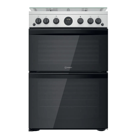
Indesit ID67G0MCX/UK Quick Manual - Page 9
Browse online or download pdf Quick Manual for Cookers Indesit ID67G0MCX/UK. Indesit ID67G0MCX/UK 25 pages.
Also for Indesit ID67G0MCX/UK: Manual (25 pages)

INSTALLATION TIPS
WARNING : This operation must be perfomed
by a qualified technician
Gas connection
The cooker should be connected to the
gas-supply by a gas safe registered installer.
Connection of the appliance to the gas
mains or liquid gas must be carried out according to
the prescribed regulation in force, and only after it is
ascertained that it is adaptable to the type of gas to
be used. If not, follow the instructions indicated in
the paragraph headed "Adaptation to different gas
types". In the case of connection to liquid gas, by
tank, use pressure regulators that conform to the
regulation in force. The gas supply must be
connected to the left of the appliance. Be sure that
the hose does not pass through the rear of the
cooker touching hot parts.
Make sure the supply pressure conforms with the
values shown in the table entitled "Caracteristics of
the burners and nozzles".
When the cooker is installed between
cabinets (recessed), the gas connection
must be effected by an approved flexible
hose with bayonet fitting
(BS 669 or EN 14800). The gas inlet for
the cookers is a threaded G 1/2 gas female
f i t t i n g .
Connecting the gas supply
To make the connection, a flexible hose should be
used corresponding to the current gas regulations
which are:
•
the hose must never be at any point in its
lenght in contact with the "hot" parts
of the cooker;
•
the hose must never be longer than 1,5 metre;
•
the hose must not be subject to any tension
or torsional stress and it must not have any
excessively narrow curves or bottlenecks;
•
the hose must be easy to inspect along its
entire length to check its condition;
•
the hose must always be in good condition,
never attempt to repair.
Adapting the cooker to different types of gas
In order to adapt the cooker to a different type of
gas with respect to the gas for which it was
produced follow these steps:
a) a) a) a) a) replace the hose holder mounted on the
appliance with that supplied in the bag of "cooker
accessories".
b) b) b) b) b) Replacing the burner nozzles on the hob:
•remove the grids and slide the burners from their
housings;
• unscrew the nozzles
using a 7 mm socket
spanner, and replace
them with nozzles for
the new type of gas
(see table 1 "Burner and
nozzle characteristics").
•replace all the
components by
repeating the steps in
reverse order.
c ) c )
c ) c )
c )
Minimum regulation of the hob burners:
• turn the tap to minimum;
• remove the knob and adjust
the regulation screw, which is
positioned in or next to the tap
pin, until the flame is small
but steady.
In the case of liquid gas, the regulation screw
must be adjusted to the minimum setting.
•
check that the flame does not turn off when
you turn the tap quickly from high to low.
d )
d )
d )
d )
d )
Regulating the primary air of the burners:
The primary air of the burners requires no regulation.
On completion of the operation, replace the old rating
sticker with one indicating the new type of gas used.
EN
9
