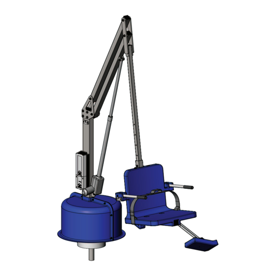
Aqua Creek F-702RLNA-02 Manual - Page 8
Browse online or download pdf Manual for Lifting Systems Aqua Creek F-702RLNA-02. Aqua Creek F-702RLNA-02 16 pages.

CONTROL ARM
LIFTING ARM
3/8" NYLOCK
NUT (2)
STEP 5: ADJUST THE SEAT POSITION
The SEAT ASSEMBLY will arrive attached to the SEAT ARM
adjusted to its highest position. To adjust the SEAT ASSEMBLY
to a lower position remove the hardware as shown below.
Slide the SEAT ASSEMBLY to its desired position (in 4 inch
increments) and reinstall the hardware. The maximum
adjustment is 16 inch (down).
DO NOT ATTACH THE SEAT ASSEMBLY ANY LOWER THAN THIS
– ALWAYS USE THE TWO (2) SUPPLIED BOLTS TO ATTACH THE
SEAT ASSEMBLY TO THE CHAIR ARM!
NOTE: For most applications, such as pools with a fl at deck,
the seat will be installed in its lowest position. For applications
where a wall or curb must be cleared the seat should be
installed in a higher position. In its highest position the seat
will clear a 26 inch [660mm] high wall (with the pull-out
legrest.
3/8" X 2"
SHOULDER BOLT
5/16" X 4 1/2"
HEX BOLT
8
Copyright © 2018 Aqua Creek Products All Rights Reserved
Revolution Assembly Instructions
Revolution Assembly Instructions
STEP 4
3/8" FLAT
WASHER (2)
SEAT ARM
STEP 4: INSTALL SEAT ARM
Locate the SEAT ARM and the following hardware:
• (2) 1/2" x 3" SHOULDER BOLT
• (2) 3/8" FLAT WASHER
• (2) 3/8" NYLOCK NUT
Install the SEAT ARM at the ends of the CONTROL
ARM and LIFTING ARM as shown in the fi gure to the
1/2" X 3"
left. Tighten the NYLOCK NUTS until snug as shown in
SHOULDER
PHOTO 4. DO NOT OVERTIGHTEN!
BOLT (2)
(NOTE: MAKE SURE THE SEAT IS FACING AWAY FROM
THE MAIN ASSEMBLY)
NOTE: FOR APPLICATIONS THAT UTILIZE MULTIPLE
SEAT ARMS (SUCH AS FOR A SLING SEAT OR THE SPA
SEAT-ARM) USE THIS STEP TO REMOVE AND REPLACE
THE SEAT ARM.
SEAT-ARM
HOLES AT 4"
INTERVALS
ALLOW FOR
ADJUSTMENT
OVER 16"
RANGE
SEAT ASSEMBLY
ADJUSTED TO
LOWEST POSITION
(SEAT WILL ARRIVE
AT HIGHEST
POSITION)
STEP 5
5/16" FLAT
WASHER (3)
5/16" NYLOCK
NUT (2)
MAIN
ASSEMBLY
Revised 11/30/18
