A.H. Systems SAS-550-2B User Manual - Page 9
Browse online or download pdf User Manual for Antenna A.H. Systems SAS-550-2B. A.H. Systems SAS-550-2B 14 pages. Active monopole antenna series
Also for A.H. Systems SAS-550-2B: Operation Manual (13 pages)

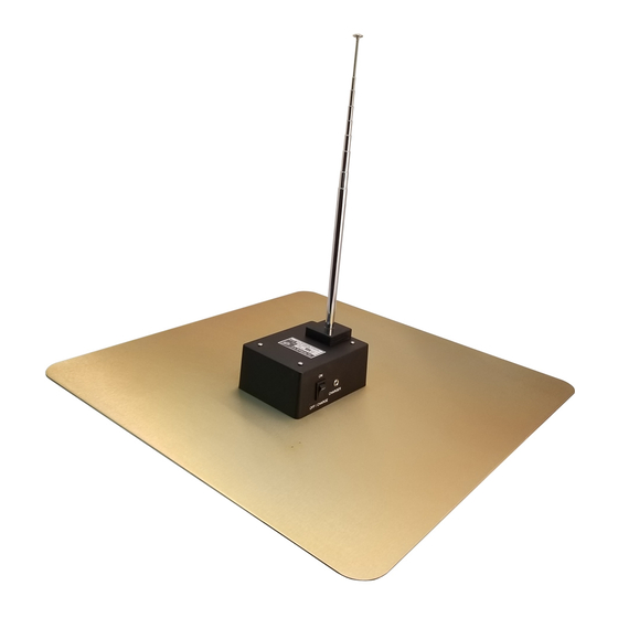
A.H. Systems Model Active Monopole Antennas
Active Monopole Calibration
The antenna factor for the rod antenna shall be determined by measuring the signal transfer
characteristics with the matching device and assuming that the antenna is a short monopole with an
infinite ground plane. Set up the monopole to be calibrated and the test equipment per Figure 3.
Allow all equipment to warm up for 30 minutes.
1) With the equipment connected as shown in Figure 1, measure the drive signal voltage V
dBV at the T-connector (A).
2) Leaving the RF output of the signal generator unchanged, transfer the 50 termination to
the T-connector (A) and transfer the receiver input cable to the signal output port (B).
Measure the output signal voltage V
3) The antenna factor (in dB) is calculated by the following equation.
NOTES – If the VSWR of the receiver or signal generator is low, pads (attenuators) may not be
needed or reduced to 6dB or 3dB. The signal generator does not need to be calibrated, but it shall
be stable per manufacturers recommendations. The 50 termination and attenuators shall have
low VSWR. The spectrum analyzer shall be calibrated and have low VSWR.
© A.H. Systems inc
REV E
Figure 1
Figure 2
in dBV.
L
AF(dB) = V
– V
– (20*Log(h
D
L
* Also referred to as a Dummy Antenna.
* Also referred to as a Dummy Antenna.
))
e
in
D
Eq.3
9
