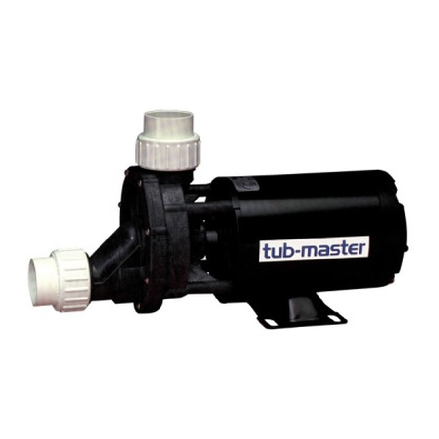
Aqua Flo VSG1432-B101 Owner's Manual - Page 4
Browse online or download pdf Owner's Manual for Water Pump Aqua Flo VSG1432-B101. Aqua Flo VSG1432-B101 5 pages. Aqua flo owner's manual pump tub-master series

W
E
ARNING
LECTRIC
PERFORMING ANY WORK ON THE PUMP UNIT
To Disassemble Pump
C
: D
AUTION
RAIN THE WATER FROM THE PLUMBING LINES BEFORE DISCONNECTING THE PUMP
MOTOR FROM POSSIBLE WATER DAMAGE
Removing the Suction Cover
1. Remove the cover by removing the screws securing the cover to the volute (casing). These screws are located at
the perimeter of the cover.
2. Note the orientation of the loose wear ring on the impeller hub before disassembling.
Removing the Impeller
1. Hold the motor shaft from rotating as follows: At the rear of the motor, insert a wide blade screwdriver in the shaft
end slot, or use a needle nose 'vise grip' or pliers to hold the shaft between the motor face and impeller sleeve
opening. Caution: Do not grip impeller sleeve.
2. Turn the impeller counter clockwise until it is completely free from the motor shaft thread.
Removing the Volute (Casing) from the Motor
1. Unscrew the four (4) bolts located at the rear of the motor. These bolts extend through the entire length of the
motor into the 4 legs of the volute.
2. When the 4 legs of the volute are completely disengaged from all the bolts, slide the volute off of the motor shaft.
Inspecting the Seal
1. Carefully examine the surfaces of the carbon disk (black rigid part of seal rotating assembly, mounted on impeller)
and the white ceramic ring (at seal stationary assembly on volute) for edge chipping, surface scratches, or uneven
wear. The surfaces should be smooth and free from damage.
2. The rest of the seal assembly should be free from cracks and should fit snugly with their respective mating parts.
3. Use alcohol wipes or isopropyl alcohol with clean 'lint free' soft cloth to clean the carbon disk and the ceramic ring
surface if reusing the same assemblies.
N
: I
OTE
T IS ADVISABLE TO REPLACE THE COMPLETE SEAL ASSEMBLY
TIME THE PUMP IS DISASSEMBLED
Removing the Seal Assemblies
1. Remove the seal rotating assembly from the impeller by carefully sliding it off of the impeller sleeve.
2. Remove the ceramic ring and rubber boot by knocking it out and/or prying it loose through the rear opening of the
volute. Be sure not to scratch or damage the ceramic surface if you are reusing this part. Caution must be used so
as not to damage the volute wall.
Installing the New Seal Assemblies
1. Seal Rotating Assembly: Carbon Disk, Spring, Steel Collar, Rubber Ring
a. Before installing the seal rotating assembly, apply water to the shaft sleeve.
b. Grasp the assembly with the carbon disk facing outward. Insert the impeller sleeve through the steel collar side.
Using a twisting motion, push until the steel collar touches the base of the sleeve.
2. Seal Stationary Assembly: Ceramic Ring, Rubber Boot
a. Before installing the stationary assembly, apply water to the rubber boot's ribbings.
b. Being careful not to damage the ceramic ring surface, press the seal assembly squarely into the seal cavity of
the volute.
Reinstalling the Volute (Casing) to the Motor
1. Align the four bolts located at the rear of the motor, with the 4 volute legs. These bolts extend through the entire
length of the motor, into the legs of the volute.
2. Pre-tighten the four bolts. Make sure that the motor shaft is accurately located in the center of (not touching) the
ceramic ring.
3. When the motor shaft is properly located, tighten the four bolts to secure the volute in place.
(continued)
Reinstalling the Impeller
1. Hold the motor shaft from rotating as follows: At the rear of the motor, insert a wide blade screwdriver in the shaft
end slot, or use a needle nose 'vise grip' or pliers to hold the shaft between the motor face and impeller sleeve
opening.
2. Thread the impeller clockwise over the motor shaft. Hand tighten only. Make sure the seal carbon disk is in contact
ASSEMBLY INSTRUCTIONS
(Including Impeller & Seal Replacement)
S
: A
HOCK
LWAYS DISCONNECT THE ELECTRICAL POWER FROM THE PUMP MOTOR BEFORE
.
.
.
(
BOTH THE CERAMIC AND CARBON SIDES
. A
LWAYS PROTECT THE
)
EVERY
