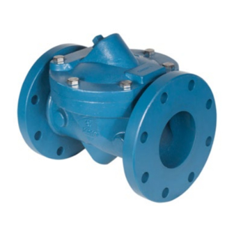
DeZurik APCO CRF-100 Installation, Operation And Maintenance Manual - Page 10
Browse online or download pdf Installation, Operation And Maintenance Manual for Control Unit DeZurik APCO CRF-100. DeZurik APCO CRF-100 14 pages. Rubber flapper swing check valves

DeZURIK
APCO CRF Rubber Flapper Swing Check Valves
Spring Return Attachment Option
The Series 100SR is designed to minimize or eliminate slam in high head applications where rapid flow
reversal causes standard swing check valves to slam. This valve has a 35° disc stroke as compared to
conventional style swing check valves, which typically have between 80° to 90° disc travel. Adding a
spring return feature causes the disc to speed up or accelerate valve closure. Having the valve closed
before reverse flow occurs can in many instances drastically reduce or even eliminate valve slam.
Note: Pump does not require shutdown or to be depressurized to make spring adjustments.
Adjustment of Closing Speed (to minimize slam)
To Increase Closing Speed:
Remove Spring Cover (54), See Figure 6.
1. Loosen Adjusting Screw Lock Nut (58), and then turn Spring Adjusting Screw (57) clockwise.
This will increase the compressive load on the spring (63), as well as apply more pressure on
the flapper to cause it to close faster and reduce slam.
2. Lock the Adjusting Screw with the Lock Nut when desired setting has been reached.
To Decrease Closing Speed: (Minimize head loss and increase flow rate)
1. Remove Spring Cover (54), see figure 6.
2. Loosen Adjusting Screw Lock Nut (58), and then turn Spring Adjusting Screw (57)
counterclockwise. This will decrease the pressure of the flapper-hence, minimize head loss and
increase flow rate.
3. Lock the Adjusting Screw with the Lock Nut when desired setting has been reached.
Maintenance (Spring Return)
There are very few moving parts in this valve – a spring adjusting mechanism where all components
are made of stainless steel, and a rubber flapper. This valve requires virtually little or no maintenance.
For periodic inspection of the rubber flapper and the body seat surface, the following procedures may
be taken: Refer to Figure 6 for details and parts.
Servicing the valve while the pipeline is under pressure can cause personal injury or
equipment damage. Relieve pipeline pressure before servicing the valve.
1. Relieve the pressure in the pipeline.
2. Isolate the Rubber Flapper Check Valve from system before loosening the Cover Bolts (4) to
remove the Cover (2).
3. Loosen each cover bolt only three full turns, then tap the side of the cover with a mallet to
separate only the valve cover from the Cover Gasket (3), this will relieve any pressure in the
valve.
4. Continue loosening to remove all cover bolts and lift off the cover. After removing the cover, the
Flapper (10) will be fully exposed and freely removed. At this point, the flapper and body
surfaces should be examined for wear.
D12007
Page 10
December 2012
