DeZurik APCO CVS-6000 Installation, Operation And Maintenance Manual - Page 8
Browse online or download pdf Installation, Operation And Maintenance Manual for Control Unit DeZurik APCO CVS-6000. DeZurik APCO CVS-6000 19 pages. Swing check valves
Also for DeZurik APCO CVS-6000: Installation, Operation And Maintenance Manual (11 pages)

DeZURIK
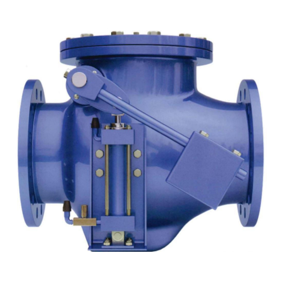
APCO CVS-6000 Swing Check Valves
Operation
The flow from the pump opens the Disc (10) and raises the Counterweight Arm (44). When the pump is
shut off, backflow pressure pushes the Disc (10) to close against the Body Seat Ring (5). As the disc is
closing, the cushion cylinder is pushed downward controlling the closing speed of the valve and can be
adjusted to suit the best performance for the installation.
CVS-6000 Valves
The side mounted pneumatic dashpot has two adjustable controlling stages. The primary control is the
Flow Control Valve (30). The second control is the internal cushion adjustment and is located in the
cylinder and provides additional control over the last 10% of disc travel.
CVS-6000B Valves
Bottom Mounted Dashpots are used when a free open and a partial control of the disc movement
during the closing cycle is required. This unique arrangement allows the valve disc to close freely for
90% of its stroke. The disc then comes in contact with the buffer plunger, which controls the speed of
closing over the last 10% of disc travel. This type of control enables the adjustment to suit the best
performance for the installation.
The bottom mounted dashpot unit has two (2) controlling stages. The primary control is the Flow
Control Valve (C1), which is located in the external piping at the cap end of the cylinder. The
secondary control is located in the head of the cylinder itself, which is the internal cushion adjustment,
which provides additional control over the last 5% of disc closing movement.
The oil operated dashpot cylinder (20) incorporates the use of a Hydro-pneumatic accumulator (50), a
device that activates and pushes the Buffer Rod (84) into the valve body. The dashpot cylinder is self-
contained and uses oil as a controlling media, creating a completely closed system which eliminates
problems of corrosion, electrolysis and mineral deposits typically present in water operated dashpots.
CVS-6100 Valves
The side mounted oil dashpot has three adjustable controlling stages. The primary control is the Timing
Valve (45). The secondary control is the Flow Control Valve (30). The third control is the internal
cushion adjustment and is located in the cylinder and provides additional control over the last 10% of
disc travel.
The dashpot cylinder is self-contained and uses oil as a controlling media, creating a completely closed
system which eliminates problems of corrosion, electrolysis and mineral deposits typically present in
water operated dashpots.
Start-up Procedure (CVS-6000 Valves)
1. Set outside lever arm 25°-30° below horizontal (not to interfere with cylinder).
2. Throttle down mainline valve on discharge side of the Swing Check Valve to approximately 1/3
open to prevent severe slamming during initial pump shutdown testing.
3. Position Counterweight (29) midway on the lever and lock in place.
4. Open flow control valve (30) two complete turns counter-clockwise from fully closed position.
See "ADJUSTMENT OF FLOW CONTROL VALVE".
5. Turn cushion adjustment screw one complete turn counter-clockwise from fully closed position.
See "OPERATION OF INTERNAL CUSHION".
6. Start and stop pump and observe rate of closing.
D12006
Page 8
December 2012
