DeZURIK
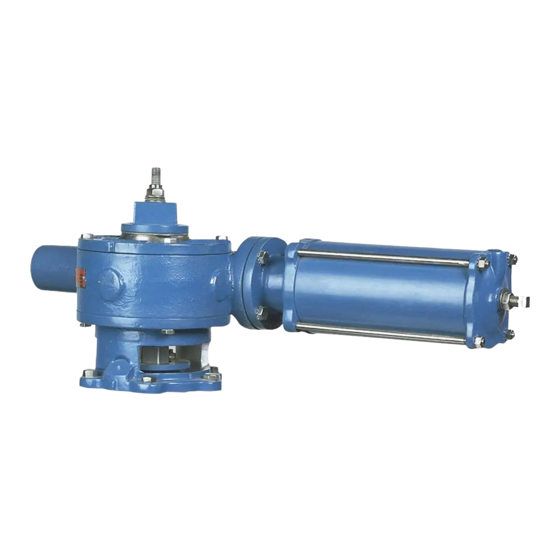
Cylinder Operated G-Series Actuator
Removing Actuator
1. Discontinue flow, relieve pipeline pressure and close valve.
Accidental operation of power actuator can cause personal injury or equipment damage.
Disconnect and lock out power to actuator before servicing.
2. Place the valve in the closed position.
3. Disconnect and lock out the pneumatic power to prevent accidental operation of the actuator.
4. Scribe a line on the valve and actuator to be used for alignment during actuator installation.
5. Remove the screws fastening the actuator adaptor to the valve or adaptor plate.
6. Lift the actuator off the valve. Be careful not to lose the actuator drive key.
Installing Actuator
1. Place the valve in the closed position.
2. Place the actuator drive key in the keyseat in the valve shaft.
3. Line up the scribe marks made during actuator removal, then set the actuator on the valve so
the valve shaft slides into the actuator gear sector. Fasten the actuator adaptor to the valve or
adaptor plate with the screws.
4. Connect the supply air tubing to the actuator.
5. Pipeline pressure and flow may now be restored.
Removing Cylinder
This procedure can be performed with the actuator installed on the valve or removed.
1. Discontinue flow and relieve pipeline pressure.
2. Apply air pressure to the port in the cylinder cap (the end farthest from the actuator housing)
until the valve has moved to the end of its stroke.
Accidental operation of power actuator can cause personal injury or equipment damage.
Disconnect and lock out power to actuator before servicing.
3. Disconnect and lock out the pneumatic power to prevent accidental operation of the actuator.
4. Disconnect the tubing from both cylinder ports.
5. Remove the extension cap from the actuator housing opposite the cylinder. On The G12
actuators, the cap is screwed on; on the G16 actuators, the cap is held on with four screws.
6. After the extension cap is removed, remove the two nuts from the end of the rack rod.
7. Remove the four screws that fasten the cylinder or cylinder adaptor to the actuator housing.
8. Carefully remove the cylinder by sliding it away from the actuator until the rack rod clears the
actuator housing.
9. See the Cylinder instructions for details on rebuilding the cylinder.
D10082
Page 6
October 2012

