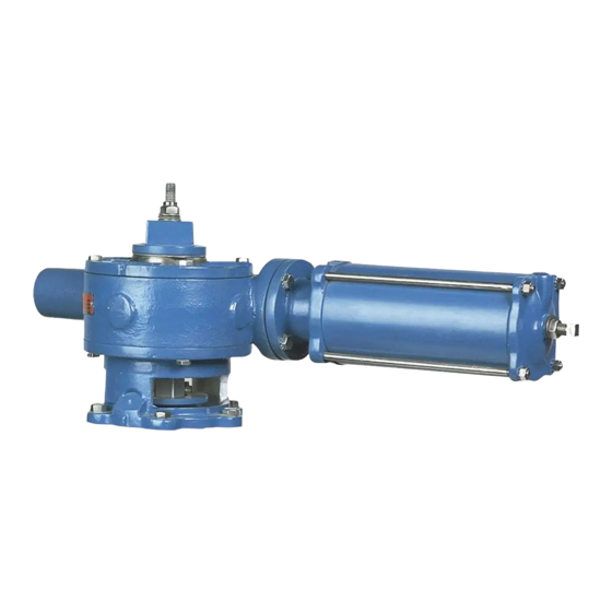
Changing Mounting Positions
6.
Remove the screws fastening the adapter to the valve. On the 4, 5, 6 and 10" (100, 125, 150
and 250mm) valves, these screws also hold the bonnet to the valve body.
This valve is a pressure vessel. On 4, 5, 6 and 10" (100, 125, 150 and 250mm) valves, the same
bolts hold both the actuator and the bonnet.
Removing the bolts on 4, 5, 6 and 10" (100, 125, 150 and 250mm) valves before relieving
pipeline pressure can result in personal injury or equipment damage.
Always relieve pipeline pressure before removing the actuator.
7. Take out the screws fastening the actuator housing to the adapter.
8. Rotate the adapter on the valve, and the actuator on the adapter until the holes line up and
the actuator is in the desired position. Replace all of the screws.
9. Find the tooth that was marked on the gear sector and count over clockwise four teeth on the
size 4 and 6 actuators, and five teeth on the size 12 and 16 actuators. This is the tooth that
will engage with the marked tooth on the rack. Install the gear sector using the new tooth
engagement, and be sure the gear sector fits on the plug stem properly.
10. Set a new cover gasket on the housing, then install and fasten the top cover on the housing;
make sure the scribe marks line up.
11. Slide the pointer and wrenching nut down the plug stud so it rests on top of the gear sector;
the pointer should point to indicate the correct valve position.
12. Place the spring washers on the plug stud as shown in Figure 5.
13. Screw the lock nut down the plug stud until it is tight and the spring washers are completely
compressed, then back the nut off one full turn.
14. Adjust the position stops. See "Position Stops" section.
Mounting Actuator in 45° Increments on 24–36" (600–900mm) Valves Only
When eccentric valves are mounted in a vertical pipeline, or mounted in a horizontal pipeline with the
plug stem horizontal, gravity can cause the plug to swing to a lower position in the valve body when the
actuator is removed. To avoid this problem, place the plug in the lowest position before removing the
actuator.
1. Discontinue flow and relieve pipeline pressure.
Accidental operation of power actuator can cause personal injury or equipment damage.
Disconnect and lock out power to actuator before servicing.
2. Disconnect and lock out the pneumatic power to prevent accidental operation of the actuator.
3. Loosen lockscrews #1 about 6 to 8 turns. Loosen lockscrews #2 about 3 turns. See Figure 4.
4. Using a soft hammer, tap the heads of the #1 lockscrews to loosen the keys.
August 2012
Cylinder Operated G-Series Actuator
(Continued)
Page 17
DeZURIK
D10022

