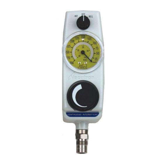
Allied Healthcare VACUTRON PEDIATRIC CONTINUOUS-INTERMITTENT Operation And Maintenance Manual - Page 8
Browse online or download pdf Operation And Maintenance Manual for Medical Equipment Allied Healthcare VACUTRON PEDIATRIC CONTINUOUS-INTERMITTENT. Allied Healthcare VACUTRON PEDIATRIC CONTINUOUS-INTERMITTENT 16 pages. Vacuum regulators for continuous or intermittent drainage

6.0
MAINTENANCE AND SERVICE:
6.1
Cover Removal and Replacement:
To remove the cover, loosen setscrew in vacuum level knob (large lower knob) and remove the knob. Remove
the two screws labeled "cover screw" on the back of the unit. Turn the selector knob (small upper knob) to
"OFF". Remove the cover and capture the spring and washer located on top of the vacuum regulator stem. Do
not misplace these items. Holding the cover and the source connection, gently pull the cover off of the body.
Before replacing the cover, replace the spring and washer. Then to replace the cover, turn the selector knob to
"OFF" and engage the two operating stem arms with the mode switch slots. Push the cover onto the body.
Install the large knob. Tighten the knob setscrew and replace the two cover screws.
Figure 4
6.2
Mode Selector Switch:
If a leak is suspected in this area, remove the cover and the hold down screw in the center of the switch (See
Figure 4). Lift the switch assembly from the center post, replace the o-rings or clean the o-rings and lubricate
them with Krytox® GPL-201 lubricant. Assemble and test for timing and vacuum level function per Section
2.0.
6.3
Safety Relief Valve:
Early models have non-adjustable relief valves. These valves have the relief ball at the top of the valve. If
you suspect a malfunction of this style relief valve, replace it.
Later models have adjustable relief valves. These relief valves can be adjusted by turning the screw at the top.
To adjust the relief valve, turn the regulator to the maximum setting and adjust the relief valve level per
Section 2.0
See Section 8.0 for ordering information. After replacement or adjustment verify that regulated vacuum
levels match Section 2.0.
6.4
Regulator Control:
The regulator controls the vacuum level when the mode switch is in the "REG" or "INT" positions. If
contamination enters the regulator, remove the hold down nut (see Figure 5). Lift the regulator from its seat.
Clean or replace regulator with a new assembly. See Section 8.0 for ordering information.
6.5
Vacuum Gauge:
6.5.1 Check the gauge for proper function. Replace the gauge if necessary. To remove the gauge, remove
the gauge screw on the back of the unit (See Figure 10). Grip the gauge by its frame and pull the gauge
straight up and away from the base (See Figure 6). Do not pull on the faceplate. To replace the gauge,
hold the gauge by its frame. Orient the gauge to read right side up when the unit is vertical. Push the
gauge column into the gauge hole. Insert the gauge screw with its plastic washer in the back of the unit
and tighten the screw. Reinstall the cover according to Section 6.1.
8
Figure 5
