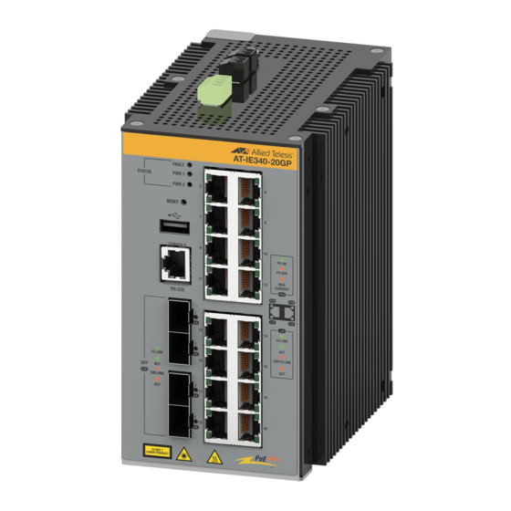
Allied Telesis IE340-12GT Quick Installation Manual - Page 2
Browse online or download pdf Quick Installation Manual for Switch Allied Telesis IE340-12GT. Allied Telesis IE340-12GT 2 pages. Industrial ethernet layer 3 switches
Also for Allied Telesis IE340-12GT: Quick Installation Manual (4 pages)

Outdoor Environment Installation
When installed in an outdoor environment, the switch must be installed in a UL-listed
Type 3X or 4X enclosure to meet safety requirements. Refer to the IE340 Series
Installation Guide.
Installing the Switch on a Concrete Wall
To install the switch on a concrete wall, perform the following procedure:
Note
The switch's maximum operating temperature depends on its orientation on the wall
and the type of enclosure. Allied Telesis recommends installing the device vertically
for best possible airflow and cooling.
1.
Place the switch on a table.
2.
Remove the pre-installed DIN rail bracket from the switch using Phillips-head
screwdriver.
3.
Install the two wall brackets to the back panel of the switch, with the four screws
included with the unit.
4.
Have a person hold the switch on the concrete wall at the selected location for the
device while you use a pencil or pen to mark the wall with the locations of the four
screw holes in the two wall brackets.
5.
Set a drill (not provided) to hammer and rotation modes. These modes break up the
concrete and clean out the hole.
6.
Use a 1/4" carbide drill bit to pre-drill the four holes you marked in Step 4.
7.
Clean out the holes with a brush or compressed air.
8.
Insert four anchors (not provided) into the holes.
9.
Have a person hold the switch on the concrete wall at the selected location while you
secure it with four screws (not provided).
Connecting the Grounding Wire
To connect the grounding wire with bare wire, perform the following procedure:
1.
Strip 2.54cm (1.0 in.) of insulation from the end of the solid grounding wire with a
wire insulator stripper.
2.54cm (1.0 in.)
2.
Loosen the grounding screw several turns with a #2 Phillips-head screwdriver.
3.
Wrap the grounding wire clockwise around the base of the grounding screw.
4.
Tighten the screw to secure the grounding wire to the switch.
5.
Connect the other end of the ground wire to a ground point at the installation site.
Preparing the DC Power Cables
A power supply is connected to the switch with two wires, one positive (+) and one
negative (-). If you are installing only one power supply to the switch, you may connect it
to either the PWR1 or PWR2 connector.
To build DC power cables for the unit, perform the following procedure:
1.
Strip 6.5mm (0.25 in.) of insulation from the end of the solid grounding wire with a
wire insulator stripper.
2.
Tightly wrap the wire strands with your finger tips.
3.
Remove the PWR1/PWR2 connector from the top panel.
4.
Loosen the wire retaining screws in the connector with #1 screwdriver.
5.
Insert the wires into the connector and tighten the retaining screws to secure the
wires.
6.
After attaching the wires to the connector, verify that there are no exposed wires or
loose wire strands.
Powering on the Switch
1.
Verify that the DC power supply is powered off. If there are two DC power supplies,
verify that both units are powered off.
2.
Connect the power cable to the PWR 1 - PWR 2 connector on the top panel.
3.
Connect the other end of the power cable to the DC power supply.
4.
Power on the DC power supplies.
5.
Wait three to four minutes for the switch to initialize its operating system.
4
Starting the First Management Session
The first management session with the switch has to be a local session, conducted through
the Console port.
To start the management session, perform the following procedure:
1.
Connect the RJ-45 connector on your management cable to the Console port on the
front panel of the switch.
2.
Connect the other end of the cable to the RS232 port on a terminal or personal
computer with a terminal emulation program.
3.
Configure the VT-100 terminal or terminal emulation program as follows:
Baud rate: 9600 bps (The baud rate of the Console port is adjustable from 1200 to
115200 bps. The default is 9600 bps.)
Data bits: 8
Parity: None
Stop bits: 1
Flow controller: None
4.
Press Enter. You are prompted for the name and password of the manager account.
5.
Enter the user name and password; The default values are:
User name: manager
Password: friend
The switch starts the local management session and displays the following prompt:
awplus>
This prompt indicates the command line interface is in the User Exec mode.
Copyright © 2020 Allied Telesis, Inc. All rights reserved.
No part of this publication may be reproduced without prior written permission from Allied
Telesis, Inc.
Allied Telesis and the Allied Telesis logo are trademarks of Allied Telesis, Incorporated. All
other product names, company names, logos or other designations mentioned herein are
trademarks or registered trademarks of their respective owners.
Allied Telesis, Inc. reserves the right to make changes in specifications and other
information contained in this document without prior written notice. The information
provided herein is subject to change without notice. In no event shall Allied Telesis, Inc. be
liable for any incidental, special, indirect, or consequential damages whatsoever, including
but not limited to lost profits, arising out of or related to this manual or the information
contained herein, even if Allied Telesis, Inc. has been advised of, known, or should have
known, the possibility of such damages.
5
6
