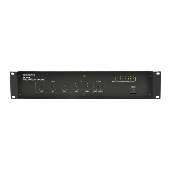
Avsl 952.864UK User Manual - Page 6
Browse online or download pdf User Manual for Amplifier Avsl 952.864UK. Avsl 952.864UK 8 pages. Loop amplifiers

Cancellation Loops
If there are areas adjacent to the loop where the magnetic field would cause problems, it is possible to avoid
this by use of a "cancellation loop", which is a narrow loop parallel to the main loop at the problem area.
This loop is the opposite polarity to the main loop and causes the magnetic field to narrow along the
adjacent edge of the main loop to control the spill of the loop field.
Connection
Connect any line sources (e.g. CD player, mp3 player) or microphones to one or more of the input channels.
If a microphone is connected, select "MIC" on the DIP switches and connect via 6.3mm jack or XLR input.
If the microphone is a condenser microphone requiring phantom power, select "PHANTOM".
For standard dynamic and battery powered microphones, set the Phantom switch to "OFF"
For line inputs, select "LINE" on the DIP switches.
For channel 1, there is an option for "PRIORITY" over the other two channels, which will mute the output of
channels 2 and 3 when there is an input to channel 1.
If the loop amplifier is to be used in conjunction with a PA system with loudspeakers, connect the line or aux
output from the PA system to a Line input on the loop amplifier via RCA, jack or XLR connection.
Ensure that this input is set to "LINE" and Phantom is set to "OFF"
Before connecting the induction loop to the amplifier, use a test meter to check the D.C. resistance in the
wire. Ensure that there are no shorted or grounded points in the wire and that the total resistance is not less
than 0.2Ω
Twist the loop wires from where the loop ends to the amplifier terminals to avoid creating an extended loop
to the area where the amplifier is situated.
With the power switched off (9), connect the loop cable to the loop terminals (12) on the rear panel of the
loop amplifier.
952.864UK, 952.867UK User Manual
