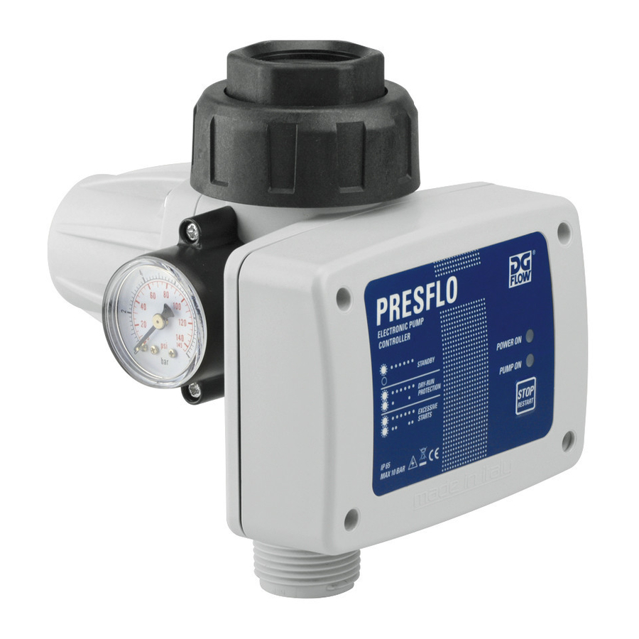
DGFLOW PRESFLO User Manual - Page 2
Browse online or download pdf User Manual for Controller DGFLOW PRESFLO. DGFLOW PRESFLO 4 pages. Electronic pump controller

Installation
Preliminary checks
®
Take the PRESFLO
out of
the packaging and check the
following:
- check for damage,
- check the RATINGS corre-
spond with those required,
- that the cable bushings and
screws are in place,
- that PRESFLO
®
's inlets and
outlets are clean and free of
any packaging materials,
- that the check valve moves
smoothly.
Hydraulic connections
the joint in two pieces allows
rapid connection to the system.
DO NOT apply sealant inside the
2-piece joint because it already
has an internal o-ring.
Orientation
®
PRESFLO
can be
installed at any angle
depending on the
ow direction, as
indicated in the diagrams.
Position
®
PRESFLO
can either be tted
directly to the pump outlet or
anywhere along the delivery
line. Never install taps between
the pump and PRESFLO
®
. Do
not install a non-return valve
®
between PRESFLO
and the
taps, meanwhile it is possible,
although not necessary, to in-
stall a non-return valve on the
suction piping of the pump.
NOTE 1 - DRY RUN PROTECTION = there is no ow and the
pressure is lower than that of the pump start-up pressure (Pm).
It occurs when there is no water. After 15 seconds PRESFLO
stops the pump and indicates an ERROR message. PRESFLO
AUTOMATICALLY tries to resume NORMAL SERVICE at intervals
of increasing time (1, 15, 30, 60 minutes and successively once
every hour - 24 H for AU/NZ -). If PRESFLO
and/or ow, NORMAL SERVICE is resumed, otherwise, the pump is
stopped again until the next attempt is made. A MANUAL attempt
to resume NORMAL SERVICE can be made at any time.
NOTE 2 - EXCESSIVE STARTS = the repeated stopping and
starting of the pump at intervals of less than 1 minute from each
other. This occurs when the ow rate is less than 2 litres/min. This
may cause damage to the pump. In event of small leaks (dripping),
Red =
20 m (65 ft)
Blue =
12 m (40 ft)
Yellow =
6 m (20 ft)
Electrical con-
nections
The electrical
connections
should be made
as indicated in the
diagram which
can also be found
on the inside of
Line
the circuit cover.
Attention! The cable
bushings and circuit board
cover must be properly
assembled and secured
in order to guarantee IP
65 grade protection of the
electrical components.
®
®
®
detects any pressure
Attention
The pressure applied
by the water column above
PRESFLO
®
must not exceed
that of the pump start-up
pressure (Pm). If, for example,
®
PRESFLO
is installed at a
height 15 m (50 ft) below that
of the highest tap in the sy-
stem, the pressure detected by
PRESFLO
®
will be approxima-
tely 1.5 bar (22 psi). A model
with Pm = 2.2 bar (32 psi)
should, therefore, be installed
in order to guarantee that the
pump is started when a tap is
turned on.
Attention
The maximum pressure
produced by the pump must be
at least 1 bar (15 psi) higher
than the start-up pressure
(Pm). If the pressure produced
by the pump is too low,
PRESFLO
®
will stop the pump
and indicate a 'dry running'
error message.
Motor
Nut
Seal
Cable bushing
®
PRESFLO
's water accumulator guarantees that the pump starts/
stops at time intervals of over 1 minute (less than 60 starts/hour)
and that FREQUENT START-UP errors do not occur. In the event of
a major leak or extended use at excessively low ow rates (less
than 2 litres/min), the pump may be started/stopped as often as
once every few seconds, putting the pump at risk of damage. In
this case, after about 40 minutes, PRESFLO
the following 30 minutes (in order to let it cool down) and indicates
an ERROR message. If the time interval between the starts-stops
is more than 10 seconds (and therefore poses less of a risk to the
®
pump), PRESFLO
will allow the pump to be used for more than
30 minutes. Once that enough time has passed to allow the pump
to cool down it is restarted AUTOMATICALLY. The pump may be
restarted MANUALLY any time.
First start-up
Priming the pump
For instructions on how to
prime ( ll) the pump, see the
pump manual.
Attention
PRESFLO
®
is tted with a
check valve: do not use the
®
PRESFLO
's outlet to ll the
pump for priming.
Switching the pump on
The red (Power On) LED lights
®
up; PRESFLO
instantly detects
that there is no pressure within
the system and
starts the pump
(the green
'Pump On' LED lights up).
If, within 15 seconds of starting
®
up, PRESFLO
does
not detect the
correct priming of
the pump, it stops the pump
and indicates a 'dry running'
error message.
Attention
When the pump is star-
ted for the rst time, it
may have to be run for
longer in order to complete the
priming procedure.
Press the
STOP/RESTART
button
to restart the
pump and
complete the
priming procedure.
®
stops the pump for
