Allied Telesis AT-AR040 Installation And Safety Manual - Page 12
Browse online or download pdf Installation And Safety Manual for Network Hardware Allied Telesis AT-AR040. Allied Telesis AT-AR040 13 pages. Network service module
Also for Allied Telesis AT-AR040: Installation And Safety Manual (12 pages)

Installation and Safety Guide
AT -AR048 LEDs
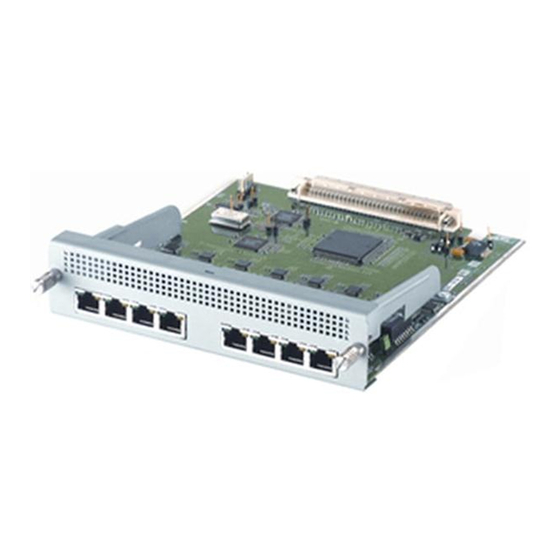
The following table describes LEDs on the AT-AR048 NSM.
LED
Active
Loop
LOS
LOF
AIS
FERF
Switch and Router LEDs
The following table describes LEDs on switches and routers that support NSMs.
LED
In Use (rear panel) Green
Swap (rear panel)
State
Function
Green
Lit when the Line Interface Unit (LIU) is receiving
a signal.
Green
Lit when any loopback is active.
Amber
Lit when the received signal is lost. This usually
indicates a network disruption, such as a cable
being disconnected or a device failure.
Amber
Lit when the DS3 framer cannot extract valid
frames from the received signal.
Amber
Lit when an Alarm Indication Signal is detected.
Amber
Lit when a Far End Receive Failure signal is
detected. This indicates the far end is receiving an
AIS, LOS, or LOF signal.
State
Off
Green
Off
Function
An NSM is installed, is receiving power, and is
operational. The NSM and its PICs are not ready
for hot swap.
No NSM is installed or the NSM is not installed
correctly. The switch or router has not
recognised the NSM.
The NSM and its PICs are ready to be hot
swapped.
The Hot Swap button must be pressed before the
NSM or its PICs can be hot swapped, or the
software release does not support hot swapping.
Hot swapping is supported by Software Version
2.3.1 or later.
11
613-000610 Rev B
