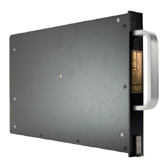
Avtech CSD-714 Selcal Installation Manual - Page 11
Browse online or download pdf Installation Manual for Media Converter Avtech CSD-714 Selcal. Avtech CSD-714 Selcal 20 pages.

- 1. Table of Contents
- 2. Description
- 3. Operation
- 4. Specifications
- 5. Installation
- 6. Installation Testing
- 7. Equipment and Accessory Part Numbers
- 8. Notes for Installation Figures
- 9. Figure 1 - Wiring Diagram
- 10. Figure 2 - Outline Drawing
- 11. Figure 3 - Code Programming
- 12. Figure 4 - 20 Db Attenuator
- 13. Figure 5 - Annunciator Output Circuits
CSD-714 Installation and Operation Manual
Power-On Self Test:
INSTALLATION
The CSD-714 is intended for mounting in the radio equipment bay of an aircraft and due to its
wide operating temperature range does not need to be in a temperature controlled environment.
Although the CSD-714 is equipped to monitor two or five inputs depending on version, it is not
necessary to use all channels.
At installation it is necessary to connect various pins in the units connector to program the
sequence necessary for a valid decode. This procedure is detailed in Note 1 for Figure 1 and in
Figure 3 of this section.
The installation wiring drawing (Figure 1) shows connection pins for airline VHF communication
transceivers which meet either ARINC characteristic 716 or 566. Other transceivers may be used,
such as HF units, if the equivalent pins are utilized.
Audio for the CSD-714 input is normally obtained from the SELCAL output of VHF and HF
receivers. The audio level at the SELCAL output is normally within the range of the input levels
accommodated by the CSD-714 and may be connected directly. If the CSD-714 is to be wired to
the squelched audio as might be found at the input to the audio selector panel, the levels are
generally greater than the maximum input rating of the CSD-714. In this case, a 10 to 1 voltage
divider (20 dB of attenuation) should be used in the audio input to the decoder. Avtech provides a
in line attenuator under the part number 1200009-000 or one may be fabricated locally using
Figure 4 as a guide. It is to be installed with the output end directly into the CSD-714 mating
connector, and the input end spliced into the audio circuit wiring. This attenuator will reduce
normal aircraft audio levels to a level compatible with the CSD-714 (100 mw into 600 ohms,
equivalent to 7.7 VRMS will be converted to 0.77 VRMS).
The assignment of codes for SELCAL operation is coordinated by SELCAL Registrar,
Aeronautical Radio, Inc., 2551 Riva Road, Annapolis, Maryland, 21401. Phone number is
(410) 266-4142. Contact them if a code has not been assigned to the aircraft. They will require
the following information:
Name of Applicant Company
Person to Contact
Aircraft Registration Number
Company Address
Intended world areas of operation
If your decoder is a 12 or 16 tone decoder.
(The CSD-714 is a 16 tone decoder)
1
Seattle, WA USA
Unit checks for valid decode code strapping upon power-on
and will latch all annunciators on if invalid.
23-21-01
Rev 1
June 1995
Page 5
