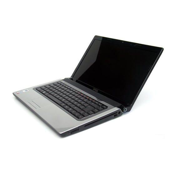
Dell 1555 - Studio - Chainlink Service Manual - Page 37
Browse online or download pdf Service Manual for Desktop Dell 1555 - Studio - Chainlink. Dell 1555 - Studio - Chainlink 50 pages.
Also for Dell 1555 - Studio - Chainlink: Service Manual (50 pages)

1 screws (10)
3 touch pad connector
5 camera cable connector 6 speaker connector
9. Carefully lift the palm rest along the rear edge, near the hinge brackets, then gently lift the palm rest to remove it from the computer.
Replacing the Palm Rest
1. Align the palm rest with the base of the computer and gently snap it into place.
2. Replace the ten screws on the palm rest.
3. Connect the touch pad cable and speaker cable to the respective system board connectors.
4. Connect the display cable, camera cable, and power button cable to the respective system board connectors (see
5. Slide the antenna cables through their cable routing (see
6. Replace the Mini-Cards (see
7. Replace the eight screws at the bottom of the computer.
8. Replace the base cover (see
Back to Contents Page
Great user manuals database on
2 power button connector
4 display cable connector
Replacing the Display
Replacing the
Mini-Card).
Replacing the Base
Cover).
UserManuals.info
Replacing the Display
Assembly).
Assembly).
