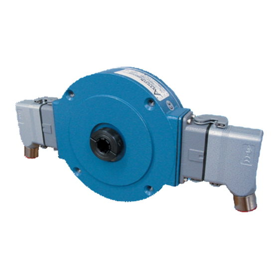
Avtron M3-H Instructions
Browse online or download pdf Instructions for Media Converter Avtron M3-H. Avtron M3-H 4 pages. Hollow shaft

Nidec-Avtron Makes the Most Reliable Encoders in the World
8 9 0 1 E . P L E A S A N T VA L L E Y R O A D • I N D E P E N D E N C E , O H I O 4 4 1 3 1 - 5 5 0 8
T E L E P H O N E : ( 1 ) 2 1 6 - 6 4 2 - 1 2 3 0 • F A X : ( 1 ) 2 1 6 - 6 4 2 - 6 0 3 7
E - M A I L : t a c h s @ n i d e c - a v t r o n . c o m • W E B : w w w . a v t r o n e n c o d e r s . c o m
DESCRIPTION
The Avtron Model M3-3, M3-4, M3-5, M3-6, M3-7, M3-8,
M3-9, M3-A, M3-B, M3-C, M3-D, M3-E, M3-F, M3-G, M3-H, and
M3-J Hollow Shaft Encoders are speed and position incremental
transducers (also known as tachometers or rotary pulse generators).
When mounted to a motor or machine, their output is directly
proportional to shaft position (pulse count) or speed (pulse rate). The
M3 operates down to zero speed and can be used for both control and
instrumentation applications.
The M3 Hollow Shaft Encoders eliminate the need for shaft couplings,
adapter flanges, or accessory mounting faces. The unit employs a
hollow shaft and clamping collar to lock the encoder to the shaft. An
anti-rotation bracket prevents rotation of the encoder while allowing
for shaft end float.
The enclosures on all Model M3s help protect the internal components
from the entry of dust and liquids.
All M3s utilize a photoelectric sensing system. All M3s can be equipped
with one or two outputs. Each output is electrically independent and
totally isolated. For many applications this feature provides a running
spare output by simply interchanging the output connectors.
The outputs can be wired as single ended single phase, single ended
two phase (A,B), or differential (A Quad B). An auxiliary output is
available (C,C) at 1/4 the base PPR for instrumentation.
Refer to separate instructions for additional information on the shaft
grounding option.
INSTALLATION CONSIDERATIONS
The M3 hollow shaft encoder requires a minimum mounting shaft
length, a minimum clearance space, and a precise shaft diameter
tolerance for proper mounting. See the table on the back page for shaft
requirements by model.
M3 PART NUMBERS AND AVAILABLE OPTIONS
Mounting
Model
Bore Size
Style
M3-
0- Non-Standard
S- End of Shaft
3- 5/8"
7- 2 3/8"
T- Thru Shaft
A- 3/4"
B- 12mm
G- End of Shaft
4- 1"
C- 16mm
with Grounding
5- 1 1/8" F- 25mm
8- 1 1/2" G- 48mm
9- 1 5/8" D- 52mm
6- 2"
E- 58mm
J- 2 1/8" H- 60mm
10 Pin Connector
MS
A- without Plug
K- with Flex. Conduit
s
B- with Flex. Conduit
Adapter
b
Adapter
L- with Plug
s
b
C- with Plug
M- without Plug
s
Output
Line Driver
Location
1- 5 to 24 VDC
L- Single output
2- 5 to 18 VDC
left side
3- 18 to 24 VDC
R- Single output
4- 5 to 24 V in,
right side
5 V out
D- Dual output
MS mini
S- Baldor Twist
P- with Plug
Lock on
V- without Plug
3 ft. Pigtail
b
side exit
bottom exit
s
b
The M3 standard flexible anti-rotation bracket will tolerate ± 0.1"
of shaft end float. For applications with larger movement, select
modification 003, torque arm mount.
CAUTION
Be careful not to damage clamping fingers during
handling. Do not tighten clamping collar before
installation onto motor shaft. Damaging clamping fingers
can affect the quality of installation.
NOTE
In some cases units are shipped with a protective plug in
the hollow shaft to help prevent damage. If it is present, it
must be removed prior to final installation.
INSTALLATION
Equipment needed for installation
Supplied:
1.
M3 Encoder
2.
Clamping Collar
3.
Anti-Rotation Bracket
4.
Thread Locker (blue)
5.
Screw, Button Hd.,
3/8-16 x .50 (2)
6.
Screw, Socket Hd. Cap.
1/4-20 x .62
Not Supplied:
5/32" Hex Wrench (T-Handle Style) (M3-B)
3/16" Hex Wrench (T-Handle Style) (M3-3, -4, -5, -A, -C, -F)
7/32" Hex Wrench (T-Handle Style)
1/4" Hex Wrench (T-Handle Style) (M3-6, -8, -9, -D, -G, -J)
5/16" Hex Wrench (T-Handle Style) (M3-7, -E, -H)
7/16" Wrench
Dial Indicator
PPR
Connector
240
600
256
1024
360
1200
480
2048
500
2500
512
Connector
6 Pin MS
EPIC
M940 replacement
M737A replacement
E- without Plug
D- with Plug
b
F- with Plug
M727A replacement
H- without Plug
J- with Plug
Encoder
Instructions
M3-3 thru M3-9
M3-A thru M3-J
HOLLOW SHAFT
7.
Washer, Flat 1/4 (2)
8.
Washer, Spring Lock 1/4
9.
Washer, Tooth Lock 3/8 (2)
10. Nut, Hex 1/4-20
11. Washer, Shoulder,
Insulating
12. Washer, Flat, Insulating
13. Anti-Seize Compound
(copper)
Modifications
000- None
028- 12.5" C-Face Mount
003- Torque Arm Mount
005- -40° C Rating
008- 4.5" C-Face Mount
009- Northstar Pinout
015- Stainless Steel Shaft
016- 8.5" C-Face Mount
5 Pin MS
Conduit Box
N- with color
W- Sealed, Pigtail
s
coded leads
X- Sealed, Industrial
s
T- with Terminal
Z- Sealed, Industrial
Block
s
s
3 ft. Flex. Cable
Connector without Plug
Connector with Plug
