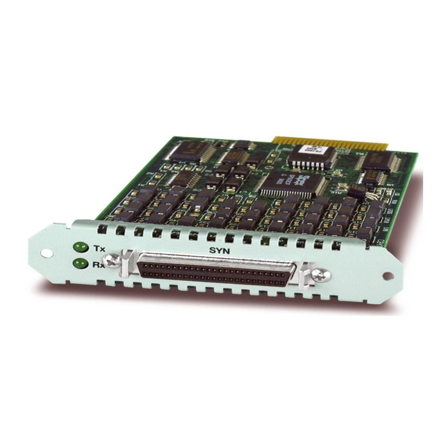
Allied Telesis AT-AR021 BRI-T Installation And Safety Manual - Page 3
Browse online or download pdf Installation And Safety Manual for Network Card Allied Telesis AT-AR021 BRI-T. Allied Telesis AT-AR021 BRI-T 8 pages. Port interface card
Also for Allied Telesis AT-AR021 BRI-T: Installation Manual (13 pages)

Installation and Safety Guide
Package Contents
The following items are included with each Port Interface Card (PIC). Contact your
authorised Allied Telesis distributor or reseller if any items are damaged or missing.
Two spring-loaded retaining thumbscrews
■
Two jumpers (AT-AR020 PRI E1/TI and AT-AR021(S) BRI-S/T only).
■
One Port Interface Card Installation and Safety Guide
■
One warranty card
■
Choosing a PIC Bay
You can install a PIC into a PIC bay on your switch or router, or into an AR040
NSM. Use the available PIC bays on the switch or router base unit before installing
any PICs into an AR040 NSM. When using an NSM, fill the NSM PIC bays starting at
bay 0. For instructions on installing an AR040 NSM into your switch or router, read
the Network Service Module Installation and Safety Guide supplied with the NSM.
Caution You cannot install PICs into an AT-AR040 NSM that has power applied to
it. This includes NSMs that have been deactivated using the hot swap button, but not
physically removed from the switch or router. To ensure that all power is removed
from the NSM bay, you must either physically remove it from the switch or router
(using the hot swap method), or disconnect all power sources to the switch or
router.
You can install a maximum of two AT-AR020 PRI E1/T1 into an AR040 NSM. The
maximum number you can install in your switch or router is four.
Caution You cannot install an AT-AR020 into an AR750S-DP that is powered by
AC power supply units.
When using AT-AR027 PICs with an AR740 and AR745 router and NSM, you can
install a maximum of four AT-AR027 PICs in the router and NSM.
3
613-000601 Rev A
