Dell S6000-ON Installation Manual - Page 9
Browse online or download pdf Installation Manual for Switch Dell S6000-ON. Dell S6000-ON 41 pages. Open networking
Also for Dell S6000-ON: Getting Started Manual (26 pages), Troubleshooting Manual (29 pages)
1
Serial Console
2
Master LED
3
Power LED
4
Fan Status LED
5
Locator LED
6
Stack ID
7
USB-A
8
USB-B Console
9
Management
LED behavior
The following S6000–ON system LED behavior is seen during ONIE operations:
Table 1. LED behavior
LED
System Status LED
Master LED
Fan LED
Power Status LED
Locator LED
Prerequisite
The following is a list of components required for a successful installation of the S6000-ON.
NOTE:
Detailed installation instructions for the S6000-ON are provided in
•
S6000–ON chassis
•
AC cables to connect the AC power source to each of the chassis' AC power supplies (country/regional configured)
•
Mounting brackets for rack installation (included)
•
Screws for rack installation and #1 and #2 Phillips screwdrivers (not included)
•
Ground cable (not included, optional)
•
Ground cable screws (included)
Description
•
Off—no power
•
Blinking green—booting or system is in Diagnostic mode
•
Solid green—normal operation
•
Solid red—critical alarm
•
Blinking red—noncritical alarm
•
Solid green—system is in Stacking Master mode
•
Off—system is in Slave mode
•
Solid green—fan is powered on and running at the expected
RPM
•
Solid yellow—fan failed including incompatible airflow direction
•
Off—no power
•
Solid green—normal operations
•
Blinking yellow—a power supply has failed
•
Off—locator function is disabled
•
Blinking blue—locator function is enabled
Site Preparations
and
Install the
S6000-ON.
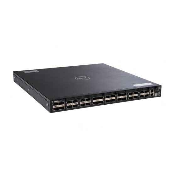
The S6000–ON system
9