Allied Telesis AT-PWR4 Installation Manual - Page 2
Browse online or download pdf Installation Manual for Power Supply Allied Telesis AT-PWR4. Allied Telesis AT-PWR4 2 pages. Auxiliary power supply for at-mcr12
Also for Allied Telesis AT-PWR4: Installation Manual (2 pages)

To apply power to an AT-PWR4 installed in an AT-MCR12 chassis, perform
the following procedure:
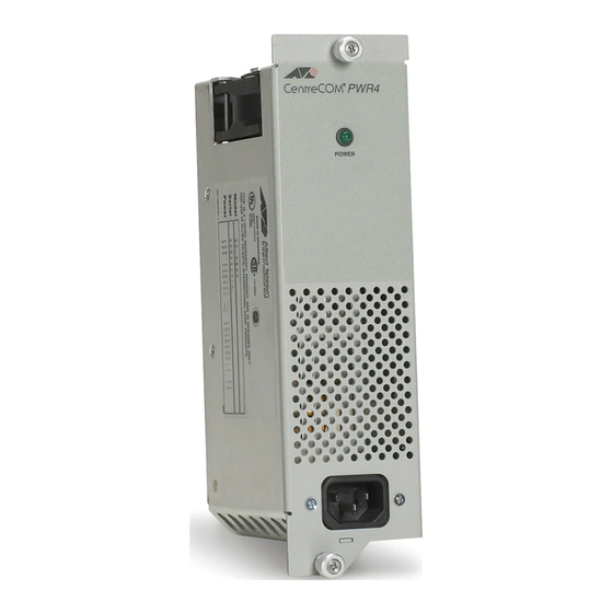
1. Connect the power cord to the power supply, as shown in Figure 4.
Figure 4 Connecting the AC Power Connector to Switch
2. Connect the power cord to an appropriate
power outlet.
3.
The power supply is self-adjusting for AC input power between 120 Volts and 240
Volts.
4.
Verify that the POWER (PWR A or PWR B) LED is green. If the LED is OFF, refer
to the following "Testing and Troubleshooting the Installation" section.
The switch is ready for network operations.
Testing and Troubleshooting the Installation
Follow the guidelines in this section for testing and troubleshooting the
installation in the event a problem occurs.
1. Verify that the
LED is green. If one of the LEDs
POWER (PWR A or PWR B)
is OFF, do the following:
❑ Check to be sure that the power supply is securely connected to the
power outlet.
❑ Check to be sure that the power supply is securely seated in the
chassis.
2. Check to be sure that the fans for both power supplies are operating. If a
fan is not operating, it is likely that the power supply has failed.
If you are still experiencing problems after testing and troubleshooting the
installation, contact Allied Telesis Technical Support at
www.alliedtelesis.com for assistance.
Warranty Registration
Allied Telesis hardware products are covered under limited warranties. Some
products have a longer warranty coverage than others.
This AT-PWR4 power supply has a limited warranty of 5 years.
All Allied Telesis warranties are subject to the terms and conditions set out on
the Allied Telesis website at www.alliedtelesis.com/warranty.
4
Technical Specifications
Physical Characteristics
Dimensions
Operating Temperature
Storage Temperature
Operating Relative Humidity
Storage Relative Humidity
Power Requirements
1225
Power Rating
Agency Certifications
Electrical Safety
Immunity
Emmission
225 mm x 61 mm x 120 mm
(8.9 in. x 2.4 in. x 4.7 in.)
0° C to 40° C (32° F to 104° F)
-25° C to 70° C (-13° F to 158° F)
5% to 90% RH (non-condensing)
5% to 95% RH (non-condensing)
100-120 VAC, 50/60 Hz, 3.0 A
220 -240 VAC, 50/60 Hz, 1.5 A
UL60950-1 (
UL
), EN60950-1 (TUV),
c
us
CSA 950
EN50082-1
EN55022-1 Class A
5
Copyright © 2007 Allied Telesis, Inc. All rights reserved. No part of this publication may
be reproduced without prior written permission from Allied Telesis, Inc.
6
