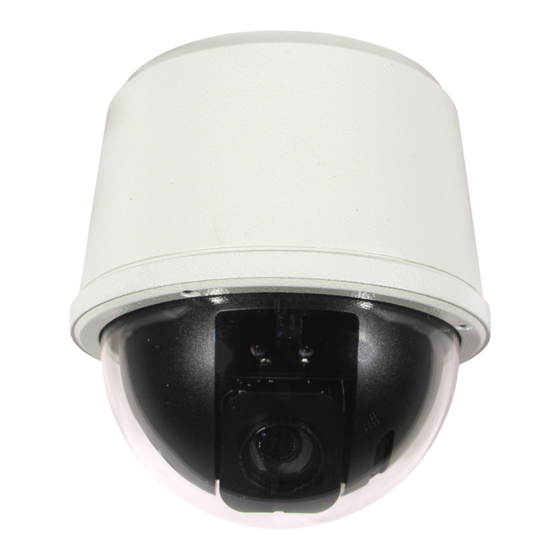
360 Vision Vision i Dome Installation & Configuration Manual - Page 3
Browse online or download pdf Installation & Configuration Manual for Security Camera 360 Vision Vision i Dome. 360 Vision Vision i Dome 20 pages.

Vision i Dome_VisionDome VR Installation Manual Ver 3.1
1 Safety and Precautions
1. Please read these notes before attempting to operate the 360 Vision VisionDome-HD, and keep for future
reference.
2. All servicing and repairs must be handled by 360 Vision Technology.
3. Avoid pointing the camera directly towards a bright light source (sunlight), or expose the camera to intensive
light situations as this may damage the camera pick-up device.
4. Installation should be carried out by suitably qualified personnel, in accordance with local codes of practice
and regulations.
5. 360 Vision Technology Limited accept no liability for any damage caused by incorrect or improper installation.
2 Housing Dimensional Drawing
External Soffit
1
210.0
9 (x4) ON
A
190.5 (7.5") PCD
B
C
D
MATERIAL:
THIS DRAWING AND ALL COPIES ARE
C COPYRIGHT PROTECTED AND
360 Vision Technology Ltd.
MUST NOT BE REPRODUCED OR SHOWN TO
Unit 7, Seymour Court,
ANY THIRD PARTY WITHOUT THE DIRECT WRITTEN
Manor Park, Runcorn, Cheshire,
A3
PERMISSION OF THE AUTHOR.
WA7 1SY. United Kingdom.
www.360visiontechnology.com
1
2
50 (2") GLAND
CLEARANCE
M12x1.5P (x3)
CABLE GLAND CONNECTION
(SEALING PLUG SUPPLIED
ON UNUSED CONNECTION)
5
10
188
SCALE 0.4
-
FINISH:
TOLERANCES:-
DO NOT SCALE
X =
0.5
ALL DIMENSIONS IN MM
X.X =
0.1
REMOVE ALL SHARP EDGES
X.XX =
0.05
2
© 360 Vision Technology Ltd.
3
-
NAME:
DATE :
ENGINEER:
K.CRAIK
210118
APPROVED:
3rd ANGLE PROJECTION
RELEASED:
3
Page 3
4
SCALE 0.4
SCALE 0.4
Weight 3.5kg
A
220118
ISS DATE
SCALE:
DESCRIPTION
0.167
VANDAL INSTALL
SOFFIT MOUNT (CEILING)
PART NUMBER:
M5727-A
4
A
FIRST ISSUE
REFERENCE
SHEET:
1 OF 2
