Miller AlumaPower 450 MPa Owner's Manual - Page 29
Browse online or download pdf Owner's Manual for Welding System Miller AlumaPower 450 MPa. Miller AlumaPower 450 MPa 49 pages. Arc welding power source. 400 volt model
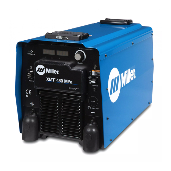
5-8. Connecting Input Power (Continued)
!
Turn Off welding power source, and
check voltage on input capacitors
according to Section 8-3 before
proceeding.
!
Installation must meet all National
and Local Codes − have only qualified
persons make this installation.
!
Disconnect and lockout/tagout input
power
before
connecting
conductors from unit. Follow estab-
lished procedures regarding the in-
stallation and removal of lockout/
tagout devices.
!
Make input power connections to the
welding power source first.
!
Always
connect
green/yellow conductor to supply
grounding terminal first, and never to
a line terminal.
See rating label on unit and check input volt-
age available at site.
1
Input Power Conductors (Customer
Notes
.
A complete Parts List is available at www.MillerWelds.com
Supplied Cord)
Select size and length of conductors using
Section 5-2. Conductors must comply with
national, state, and local electrical codes. If
applicable, use lugs of proper amperage
capacity and correct hole size.
Welding Power Source Input Power
Connections
2
Strain Relief Kit Supplied With Machine
input
Install strain relief of proper size for unit and
input conductors. Route conductors (cord)
through strain relief. Tighten strain relief.
3
Welding Power Source Grounding
Terminal
4
Green Or Green/Yellow Grounding
Conductor
green
or
Connect green or green/yellow grounding
conductor to machine grounding terminal
first.
5
Input Filter Board
6
Welding Power Source Line Terminals
7
Input Conductors L1, L2, L3
Connect input conductors L1, L2, and L3 to
welding power source line terminals.
Reinstall side panel on welding power
source.
Disconnect
Device
Input
Connections
8
Disconnect Device (switch shown in
the OFF position)
9
Disconnect Device Grounding Terminal
10 Disconnect Device Line Terminals
Connect green or green/yellow grounding
conductor to disconnect device grounding
terminal first.
Connect input conductors L1, L2, and L3 to
disconnect device line terminals.
11 Over-Current Protection
Select type and size of over-current protec-
tion using Section 5-7 (fused disconnect
switch shown).
Close and secure door on disconnect device.
Follow established lockout/tagout proced-
ures to put unit in service.
Work like a Pro!
Pros weld and cut
safely. Read the
safety rules at
the beginning
of this manual.
OM-257219 Page 23
Power
Input5 2013−04