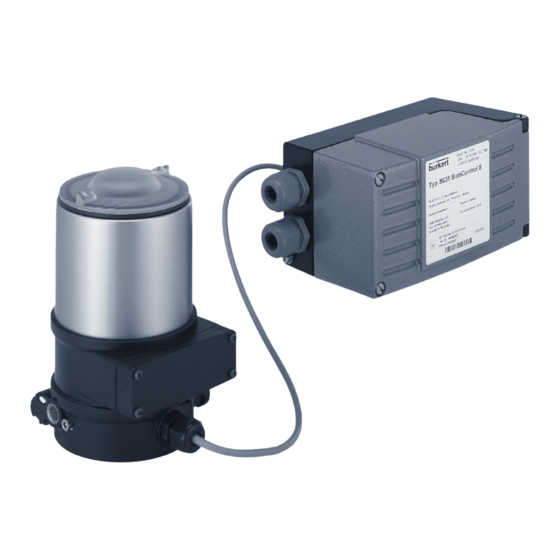
Burkert 2103 Series Quick Start Manual - Page 15
Browse online or download pdf Quick Start Manual for Valve Positioners Burkert 2103 Series. Burkert 2103 Series 19 pages. Remote-positioner, installation on process valves with internal air flow
Also for Burkert 2103 Series: Additional Instructions (12 pages)

Type 2103, 2104, 2105
2. Welding tank bottom body into the pipeline:
→ Weld in tank bottom body.
Ensure installation is de-energized and low-vibration.
After welding in the valve body:
Install the diaphragm and the actuator.
7.6
Installation of the actuator (welded or
glued body)
NOTICE!
Damage to the diaphragm or the seat contour.
▶ When installing the actuator, ensure that the valve is open.
Installation for actuator with control function A:
→ Control function A pressurize the pilot air port 1 with compressed
air (5,5 bar): valve opens.
→ Place actuator on the body
→ Lightly cross-tighten the body screws until the diaphragm lies
between the body and actuator. Do not tighten the screws yet.
→ Actuate the diaphragm valve twice to position the diaphragm
correctly.
→ Tighten body screws without pressurization in diagonal pairs in
three stages (approx. 1/3, approx. 2/3, 3/3 of the tightening torque),
according to Table ( see "Tab. 3"). The diaphragm should be
positioned and pressed evenly all around the actuator and body.
Installation for actuator with control functions B and I:
→ Place actuator on the body
→ Gently tighten the body screws in diagonal pairs without pres-
surization until the diaphragm lies between the body and actuator.
Do not fully tighten the screws yet.
Installation
→ Pressurize pilot air port 1 of the actuator with compressed air
(5,5 bar).
→ Actuate the diaphragm valve twice to position the diaphragm
correctly.
→ Tighten body screws with pressurization in diagonal pairs in three
stages (approx. 1/3, approx. 2/3, 3/3 of the tightening torque),
according to Table ( see "Tab. 3"). The diaphragm should be
positioned and pressed evenly all around the actuator and body.
Pilot air port
CFA, CFB, CFI
Fig. 12: Pilot air port
Orifice DN
Tightening torques for diaphragms [Nm]
(diaphragm size)
EPDM/
FKM
8
2.5
15
3.5
20
4
25
5
32
8
40
8
50
12
Tab. 3:
Tightening torques for diaphragms
→ A tolerance of +10% of the respective tightening torque
applies to all values.
english
1
PTFE / advanced PTFE /
laminated PTFE
2.5
4
4.5
6
10
10
15
15
