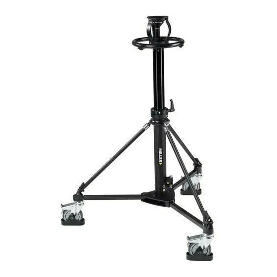
Miller 481 Operator's Manual - Page 4
Browse online or download pdf Operator's Manual for Camera Accessories Miller 481. Miller 481 8 pages. Combination pedestal

SET-UP (CONT)
•
Peel off Miller label (if applicable) from the dolly
centre hub to reveal the 12.5mm hole. (Fig 4.)
•
Remove Pedestal Column and Spider Legs from
the packing box.
•
Line up Column to the dolly centre hub, insert M12
bolt into the 12.5mm hole. (Fig 5.&6.)
•
Tighten the bolt but not fully with the supplied
10mm Hexagon Key.
•
Align the Spider Foot on to the ball of dolly end
(Fig 7.). Pull the Rubber Stirrup up and over the
end shoulder of Spider Foot. (Fig 8.) Repeat for the
remaining two spider legs.
•
Fully tighten the bolt and check that the Column is
secure.
•
Raise and lock the (airless) Pedestal Column in the
highest position using the Column Clamp Handle.
•
Use a High Pressure Pump and connect it to the
Schrader Valve on the Air Pressure Block. (Fig 9.)
Fig 6.
Fig 9.
Fig 7.
Using pump bring the air pressure to the desired level
depending on the camera load that is going to be used.
During detaching of the pump there is some air leaving
the system, therefore, we recommend putting extra air in
the system and let some air out when fine tuning balance
of the camera with its accessories.
Now the Combination Pedestal is set up in its standard
configuration on the Miller Studio Dolly range.
Fig 4.
Fig 5.
Fig 8.
