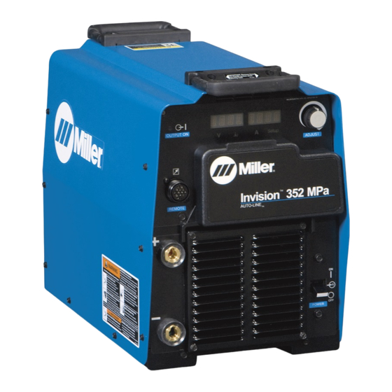
Miller Invision 352 MPa Auto-Line CE Owner's Manual - Page 20
Browse online or download pdf Owner's Manual for Inverter Miller Invision 352 MPa Auto-Line CE. Miller Invision 352 MPa Auto-Line CE 48 pages.
Also for Miller Invision 352 MPa Auto-Line CE: Owner's Manual (44 pages), Owner's Manual (44 pages)

5-1. Important Information Regarding CE Products (Sold Within The EU)
A. Information On Electromagnetic Fields (EMF)
!
This equipment shall not be used by the general public as the EMF limits for the general public might be exceeded during welding.
This equipment is built in accordance with EN 60974−1 and is intended to be used only in an occupational environment (where the general public
access is prohibited or regulated in such a way as to be similar to occupational use) by an expert or an instructed person.
Wire feeders and ancillary equipment (such as torches, liquid cooling systems and arc striking and stabilizing devices) as part of the welding
circuit may not be a major contributor to the EMF. See the Owner's Manuals for all components of the welding circuit for additional EMF exposure
information.
S
The EMF assessment on this equipment was conducted at 0.5 meter.
S
At a distance of 1 meter the EMF exposure values were less than 20% of the permissible values.
B. Information On Electromagnetic Compatibility (EMC)
!
This Class A equipment is not intended for use in residential locations where the electrical power is provided by the public low−
voltage supply system. There may be potential difficulties in ensuring electromagnetic compatibility in those locations, due to
conducted as well as radiated disturbances.
This equipment complies with IEC 61000−3−12 provided that the short−circuit power Ssc is greater than or equal to 4,798,364 at the interface
point between the user's supply and the public system. It is the responsibility of the installer or user of the equipment to ensure, by consultation
with the distribution network operator if necessary, that the equipment is connected only to a supply with a short−circuit power Ssc greater than
or equal to 4,798,364.
5-2. Serial Number And Rating Label Location
The serial number and rating information for this product is located on the rear panel. Use rating label to determine input power requirements and/or
rated output. For future reference, write serial number in space provided on back cover of this manual.
5-3. Dimensions And Weight
Hole Layout Dimensions
A
11-3/4 in. (298 mm)
B
1-11/16 in. (42 mm)
C
15-3/4 in. (400 mm)
D
19-3/32 in. (485 mm)
E
8-11/16 in. (221 mm)
F
1-17/32 in. (39 mm)
G
1/4-20 UNC -2B thread
Weight
94.8 lb (43 kg)
OM-245 171 Page 16
SECTION 5 − INSTALLATION
F
D
C
B
A
E
G
12-1/2 in.
(318 mm)
804 801-A
24 in.
(610 mm)
(432 mm)
17 in.
