Chromalox 2110 Instruction Manual - Page 6
Browse online or download pdf Instruction Manual for Temperature Controller Chromalox 2110. Chromalox 2110 20 pages.
3. Installation and Wiring
Sensor and Control Type Selection
Switches
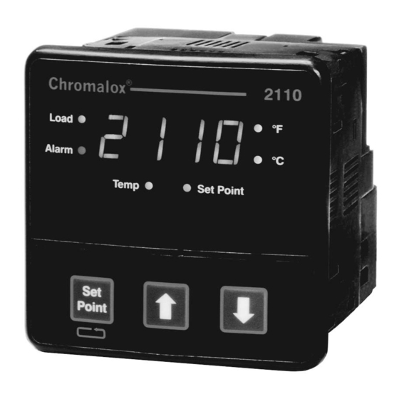
Set the Chromalox 2110 controller's configuration via
mechanical dip switches, located on the bottom of
the unit. Factory settings are J, TC, °F, and PI Control.
Switches are easier to set before mounting.
To change the switch settings, first disconnect all wir-
ing and power from the unit. Adjust switch settings as
follows:
Switch
Function
A
Thermocouple
B
Input Type
C
Temperature Units
D
Control Type
If input type is thermocouple, switch A selects either
thermocouple type J or K.
Switch B selects input type thermocouple or RTD
(resistance temperature detector). Note: If RTD is se-
lected, switch A is ignored.
Switch C selects temperature units °F or °C.
Switch D selects either PI (Proportional-Integral) or
ON-OFF control.
J
K
TC
RTD
˚C
˚F
ONOF
PI
Figure 3.1
Default Dip Switch Settings
Setting
Factory
Options
Setting
J or K
J
TC or RTD
TC
°F or °C
°F
ON-OFF
PI
or PI
J
K
TC
RTD
˚C
˚F
ONOF
PI
Mounting
Two mounting collars securely hold the 2110 controller
in the mounting hole. Remove these mounting collars
before installation.
Removing Mounting Collars
1. To remove the rear collar, press the sides of the col-
lar. This releases holding tabs on the top and bot-
tom of the collar.
2. Slide the collar off the back of the unit.
3. Slide the front collar off the back of the unit.
Front Collar
Rear Collar
Press In
Figure 3.2
Removing Mounting Collars
4
Press In
Holding
Tabs