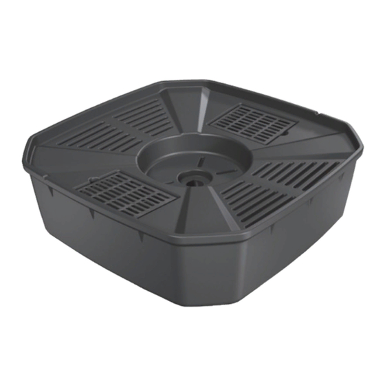
AquaScape AquaBasin 98135 Installation & Maintenance Instructions Manual - Page 5
Browse online or download pdf Installation & Maintenance Instructions Manual for Outdoor Fountain AquaScape AquaBasin 98135. AquaScape AquaBasin 98135 12 pages.

How to Assemble
the AquaBasin
™
Ceramic Bubbler
90° Barbed
How to Hook Up a Ceramic Bubbler
1) The AquaBasin
is designed with two removable grates for
™
easy pump access. Connect the Ceramic Bubbler Plumbing
Assembly, as shown above (item #98202 sold separately)
and place the pump and plumbing inside the AquaBasin
(Fig. 14) Note: Remove the top of the 1" bulkhead fitting
before placing in the AquaBasin
Slip fitting on the bulkhead. (Fig. 14)
2) Place the end of the bulkhead through the hole in the center
of the AquaBasin
™
3) Next, place the ceramic bubbler on the AquaBasin
the bulkhead through the bottom of the bubbler. (Fig. 15)
4) Take the top of the bulkhead that was removed earlier and
tighten the bulkhead at the bottom of the ceramic bubbler.
(Fig. 16) Insert the 24" PVC stand pipe into the MPT x Slip
fitting. (Fig. 17) The stand pipe will prevent water from
completely draining the bubbler and will assist in creating
the rippling effect at the top of the bubbler. Note: You can
trim the stand pipe to adjust the desired effect.
5) It is recommended that tall or oddly shaped pieces be set in
the middle and backfilled with gravel to prevent the piece
from falling over. If you do not have to backfill around the
decorative, simply fill the recessed area with gravel as a
base to set the fountain. Make sure the bubbler is level side
to side and front to back. Shims should be used to level the
ceramic bubbler. Failure to level the bubbler can result in an
uneven water flow off the ceramic bubbler.
6) Now that everything is in place, you can now finish
covering the top of the AquaBasin
The AquaBasin
is designed with two underside supports
™
to help support heavier pieces. If you decide to modify
your AquaBasin
, be sure to locate and identify these two
™
supports and DO NOT drill or puncture through the supports.
Doing so will cause the unit to leak.
Elbow
and screw in the 1" MPT x
™
. (Fig. 14)
with gravel.
™
PVC Extension
Tube
MPT x Slip
Fitting
Bulkhead
MPT x Barb
Fitting
Tubing
.
™
and pull
™
Fig. 14
Fig. 15
Fig. 16
Fig. 17
