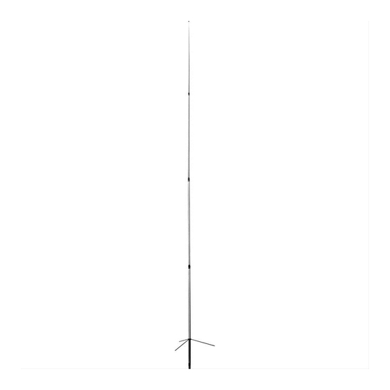
Diamond Antenna X500HNA Operation Instructions
Browse online or download pdf Operation Instructions for Antenna Diamond Antenna X500HNA. Diamond Antenna X500HNA 4 pages. 2m/70cm dual band high performance gain vertical antenna direct joint system frp outershell liner phase shifter system
Also for Diamond Antenna X500HNA: Manual (3 pages)

XSOOHNA
2M/70CM DUAL BAND HIGH PERFORMANCE GAIN VERTICAL ANTENNA
DIRECT JOINT SYSTEM
FRP OUTERSHELL
LINER PHASE SHIFTER SYSTEM
OPERATION INSTRUCTIONS
DIAMOND
ANTENNA
®@ Description
Newly developed Linear Phase Shift technology and
Direct Joint structure
by three-piece
FRP
outershell
enable to achieve the following performance.
1)2m 5/8 wave three-element C-Load and 70cm 5/8 wave
eight-element strucutre.
2)High
performance
and
high
maximum
power
rating at 2m and 70cm bands.
3)Low
vswr
and broader
coverage
at 2m
and 70cm
bands.
4)Overlapping three-piece FRP
outershell structure is
strong enough to compete
with one piece structure.
5)Ring gasket provides perfect waterproof.
6)Ideally tapered FRP outershell has enough thickness
to withstand strong wind and avoid unwanted QSB.
7)Joint bracket
can be fastened securely by special
wrench attached.
8)DC
ground
structure
of
the
antenna
protects
transceiver
from
high
voltage
caused
by thunder
lightning.
9)Feedpoint connector is being exposed downward
at
the
bottom
of
support
pipe to
make
antenna
installation or detachment easier.
10)With optional 2m/70cm duplexer, two bands can be
transmitted
simultaneously,
or
one
band
can
be
transmitted simultaneously while receiving the other
band.
@ Assembly
Note ; Be sure to assemble from upper element. If the
antenna is being assembled from lower element, element
can not be pulled out from outer shell and fastened
properly.
1)Put
special
wrenches
on
upper
and
center
FRP
outershells as shown in the Fig. 1. Use small diameter
section of the wrench.
Upper FRP
outershell
Center FRP
outershell
Special wrench
Fig. 1
2)Connect upper element in the upper FRP outershell
and center element in the center
FRP outershell with
screwdriver.
Upper element
Upper FRP.
element
outershell
Center FRP
Center
outershell
Screw driver
Fig. 2
3)After connecting
these two elements in the outershells,
fasten upper FRP outershell joint bracket with special
wrenches as shown in the Fig. 3.
Fasten the bracket thoroughly until there is no gap
between each part of the bracket.
4) After fastening the bracket, detach the wrenches from
the outershells as shown in the Fig. 4.
5)Connect center element in the center FRP outershell
and lower element in the lower FRP
outershell the
same way as section 2,3 but use larger diameter section
of the wrenches at this time as shown in the Fig. 5.
Lower FRP
Lower
Center
Center FRP
outershell
element
element
outershell
Larger diameter-
Larger diameter
section of
section of
the wrench
:
the wrench
Screw driver
Fig. 5
6)Attach
three
radial
elements
with
the wrench
as
shown in the Fig. 6.
7)Attach mast brackets on support pipe and fix them.
8)Attach assembled
antenna
on mast as shown in the
Fig. 8.
In installing the antenna be sure to take whole balance
into account.
Mast
SS
bracket
Mast
Mast
|
bracket
Zw
Fig. 7
9)Then
connect
coaxial
cable
with
N
connector
to
feedpoint section at the bottom of the antenna through
waterproof sleeve as shown in the Fig. 9.
10)After connecting coaxial cable, fix waterproof sleeve
to the bottom of support pipe with a screw.
Turn connected coaxial cable once to make a loop at
right below the antenna
as shown in the Fig. 10 to
escape excess load from the cable.
Mast |
Support
|
pipe
Mast
Support pipe
Waterproof sleeve
Coaxial cable —
=A
Make a loop 6
Fig. 9
Fig. 10
