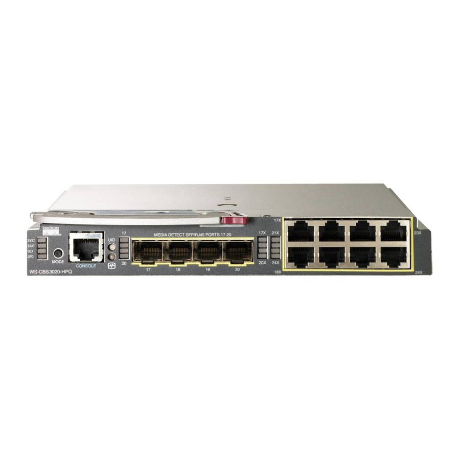
HP 3020 - Cisco Catalyst Blade Switch Getting Started Manual - Page 4
Browse online or download pdf Getting Started Manual for Switch HP 3020 - Cisco Catalyst Blade Switch. HP 3020 - Cisco Catalyst Blade Switch 11 pages. Cisco catalyst blade switch 3020 for hp getting started guide
Also for HP 3020 - Cisco Catalyst Blade Switch: Frequently Asked Questions (4 pages), Setup Poster (9 pages)

Cisco Catalyst Blade Switch 3020 for HP Getting Started Guide [Cisco Catalyst Blade Switch 3000 Series] - Cisco Systems
http://www.cisco.com/en/US/products/ps6748/products_getting_started_guide09186a00806c38a8.html (4 of 11)4/19/2007 10:27:48 AM
Switch Module IP Addresses
IP addresses can be assigned to two of the switch module interfaces:
•
The fa0 Ethernet interface. This Layer 3 Ethernet interface is connected to the Onboard Administrator through which you can manage the switch module. It is used only for switch module management traffic, not for data traffic.
•
The VLAN 1 interface. You can manage the switch module from any of its external ports through VLAN 1.
If you want to assign the VLAN 1 IP address through Express Setup, you must start that process immediately after installing the switch module in the blade server. If you miss the opportunity to have the IP address assigned in this way, you can remove and then re-install the switch module. See the
"Running Express Setup" section
for instructions.
When you install the switch module, you need to determine whether the Onboard Administrator is connected to a network in which a DHCP server is also connected or if the Onboard Administrator has been configured as a DHCP server. If either of these conditions is true, the switch module
automatically obtains an IP address for its fa0 Ethernet interface that is connected to the Onboard Administrator. In this case, a VLAN 1 IP address is not assigned, and to set up the switch module by using the Device Manager you must use the fa0 interface IP address that the DHCP server assigns.
See the
"Using the Onboard Administrator to Assign an IP Address to the Switch Module fa0 Interface" section
5 Running Express Setup
You need to supply this equipment to run Express Setup:
•
PC
•
Ethernet (Category 5) straight-through cable (as shown)
Before you run Express Setup, you must set up your switch module to communicate with a Hyperterminal program.
Note The initial configuration assumes that the switch module was never configured, that it is in the same state as when it was received, and that it is not configured with a default username and password.
Note To set up the switch module by using the command-line interface (CLI), see the switch module hardware installation guide on cisco.com.
Information You Need to Run Express Setup
You need this information about your switch module from your system administrator before you complete the setup program:
•
Fixed IP address
•
Subnet mask (IP netmask)
•
Default gateway IP address
You can also configure these optional parameters through the Express Setup program:
•
Local access password
•
Telnet access password
•
Names of the SNMP read and write community strings if you are going to use a network-management program like CiscoWorks.
•
Host name, system contact, and system location
When you first set up the switch module, you can use Express Setup to enter the initial IP information. Doing this enables the switch module to connect to local routers and the Internet. You can then access the switch module through the IP address for further configuration.
Using Express Setup to Assign a VLAN 1 IP Address to the Switch Module
Use these steps to assign an IP address to the VLAN 1 interface through Express Setup. You must start these steps immediately after you have installed the switch module (see the
Note If approximately 2 minutes pass after you press the Mode button, obtaining the VLAN 1 IP address through Express Setup is no longer possible unless you remove and then re-install the switch module.
To prepare the switch module:
Step 1 Verify that no devices are connected to the switch module, because during Express Setup, the switch module acts as a DHCP server. If your PC has a static IP address, before you begin you should change your PC settings to temporarily use DHCP.
As the switch module powers on, it begins the power-on self-test (POST), a series of tests that runs automatically to ensure that the switch module functions properly.
Step 2 Wait for the switch module to complete POST. It might take several minutes for the switch module to complete POST.
Step 3 Verify that POST has completed by confirming that the system and status LEDs remain green.
If the switch module fails POST, the system LED turns amber. If the POST fails, see the
Step 4 Press and hold the Mode button until the four LEDs next to the Mode button turn green. This takes approximately 3 seconds.
1
Mode button
Step 5 Release the Mode button.
If the LEDs next to the Mode button begin to blink after you press the button, release it. Blinking LEDs mean that the switch module has already been configured and cannot go into Express Setup mode. For more information, see the
Step 6 Connect a straight-through Category 5 Ethernet cable (not provided) to any Ethernet port on the switch module front panel and to the Ethernet port on the PC. (See
Figure 5 Connecting the Ethernet Cable from a PC to a Switch Module Ethernet Port
for how to set up the switch module if the IP address is being assigned dynamically.
"In Case of Difficulty" section
to determine a course of action. POST errors are usually fatal. Call Cisco Systems immediately if your switch module fails POST.
"Installing the Switch Module in the Blade Server"
section).
"Resetting the Switch Module"
Figure
5.)
section.
